

 English
 Español
 عربى
عربى
 русский
Industry knowledge
How Voltage Class Determines Power Cable Construction from the Inside Out
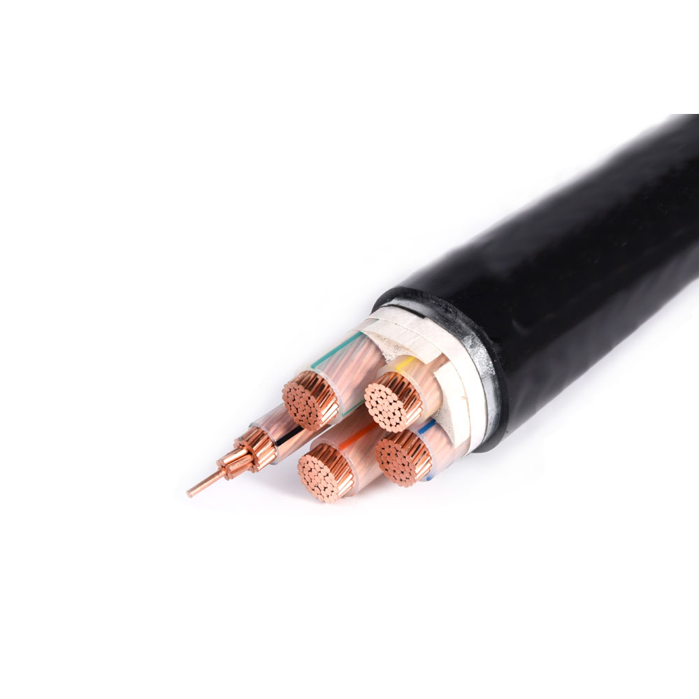
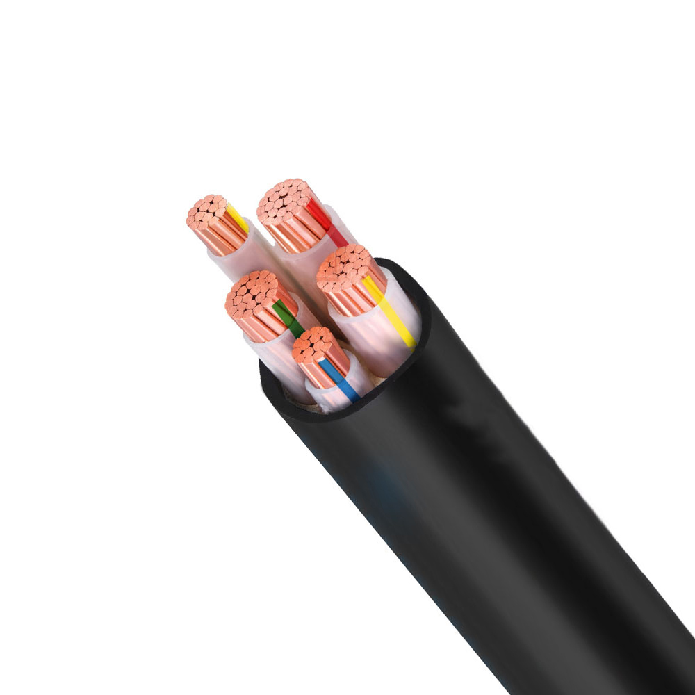
Voltage classification is the single most consequential design parameter for a power cable, and it drives construction decisions at every layer — conductor, insulation, shielding, and jacket. Power cables are broadly divided into low voltage (LV, up to 1 kV), medium voltage (MV, 1 kV to 35 kV), and high voltage (HV, above 35 kV). Each step up in voltage class introduces construction requirements that go well beyond simply increasing the insulation wall thickness.
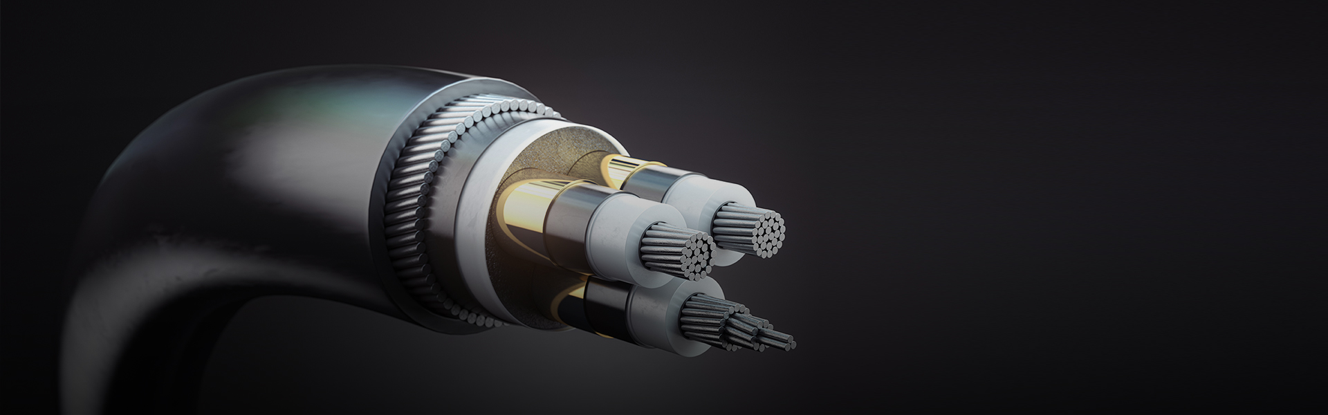
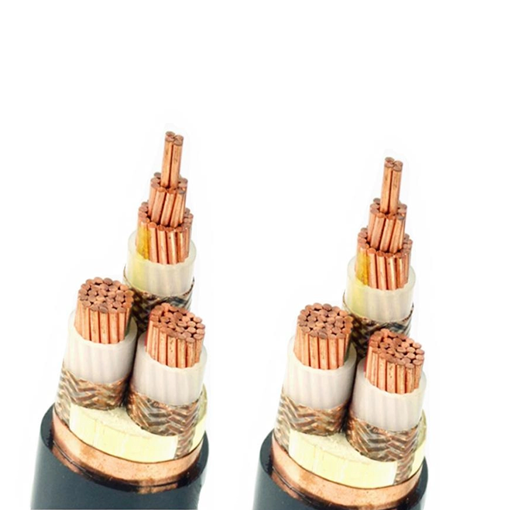
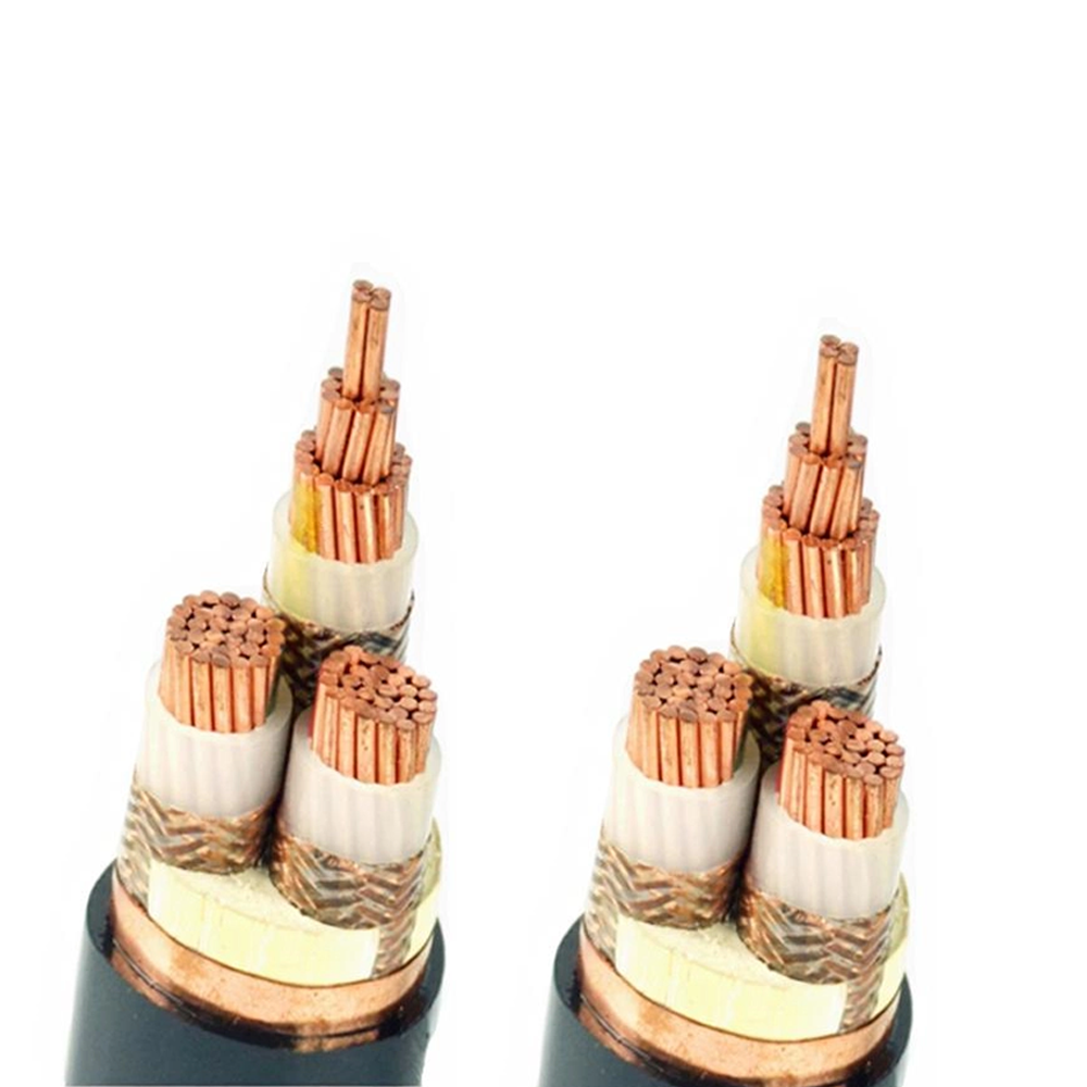
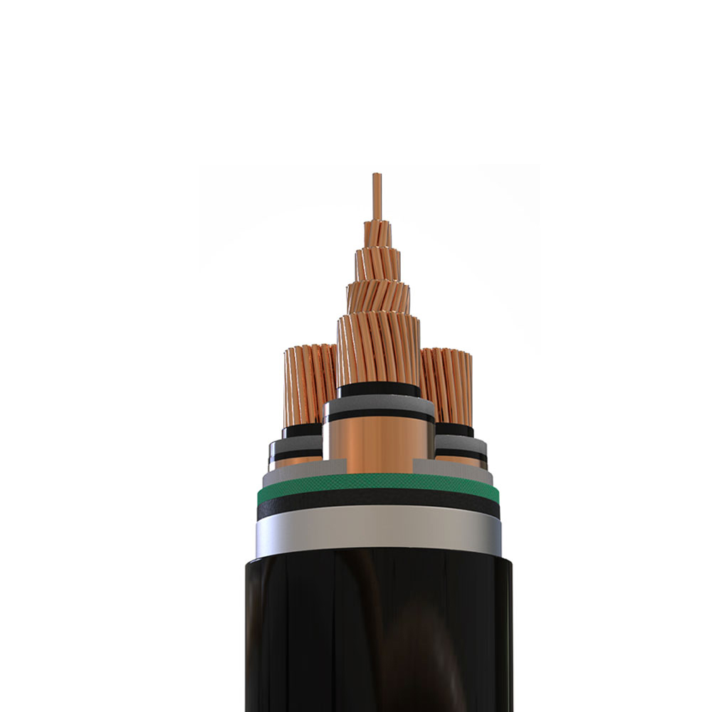
At the low-voltage level, the primary insulation function is to prevent contact with energized conductors and withstand the modest electric field gradients present. PVC and XLPE insulation walls of 0.7–1.0 mm are sufficient for 0.6/1 kV rated cables. The electric field distribution at this voltage is relatively uniform, and there is no requirement for field-grading layers. Medium-voltage cables, however, operate under electric field intensities where field concentration at conductor surface irregularities — strand edges, surface oxidation, microscopic protrusions — can initiate partial discharge that erodes insulation over time. This is why MV cables require a conductor screen: a layer of semiconducting compound applied directly over the conductor that smooths the electric field by presenting a continuous, uniform equipotential surface to the insulation. A corresponding insulation screen on the outer surface of the insulation performs the same function at the insulation-shield interface.
The insulation screen in MV cables must be bonded (non-strippable) or semi-bonded (strippable) depending on the termination method. Non-strippable screens require cutting tools and careful technique at cable ends to avoid nicking the insulation surface; strippable screens allow the semiconducting layer to be peeled away cleanly, but introduce a defined interface that must be managed to prevent moisture ingress at the screen-insulation boundary. At voltages above 15 kV, the metallic screen over the insulation screen must carry the full capacitive charging current of the cable, which becomes significant over long cable runs — a factor that determines the screen conductor cross-section independently of any fault current requirement.
Comparing XLPE and EPR Insulation in Medium-Voltage Power Cable Applications
For medium-voltage power cables, the choice between cross-linked polyethylene (XLPE) and ethylene propylene rubber (EPR) insulation is one of the most consequential material decisions, and it is frequently made on the basis of price alone — which consistently leads to performance mismatches in demanding environments. Each material has a genuinely different performance profile that maps to specific application conditions.
| Property | XLPE | EPR |
| Max Conductor Temperature (Continuous) | 90°C | 90°C |
| Dielectric Constant (εr) | ~2.3 (very low) | ~2.8–3.5 (moderate) |
| Water Tree Resistance | Moderate (requires tree-retardant grades for wet environments) | Excellent (inherently resistant) |
| Flexibility | Stiff, especially at low temperatures | Flexible across wide temperature range |
| Capacitive Charging Current | Lower (due to low εr) | Higher (limits usable cable length at HV) |
| Typical Cost Relative to XLPE | Baseline | 20–40% premium |
The most practically significant difference between the two materials is water tree resistance. Water trees are dendritic degradation channels that propagate through polyethylene-based insulation in the presence of moisture and AC electric field stress. Standard XLPE is susceptible to water treeing over service periods of 10–20 years in wet or direct-buried installations. Tree-retardant XLPE (TR-XLPE) compounds with additives that inhibit tree initiation are available and widely used in utility distribution cables, but they add cost and require the manufacturer to source and qualify specific compound formulations. EPR, being a rubber compound with fundamentally different molecular structure and moisture permeability characteristics, is inherently resistant to water treeing without additional additives. For cables installed in direct burial, flooded conduits, or submarine applications, EPR's moisture resistance makes it the technically correct choice regardless of the cost premium.
XLPE's lower dielectric constant gives it an advantage in transmission efficiency over long cable runs at medium and high voltage, because capacitive charging current — which flows even when no load is connected — is proportional to the dielectric constant. In cable systems where charging current represents a meaningful fraction of the cable's thermal ampacity (typically cables longer than 10–15 km at 33 kV), XLPE's lower εr translates directly into usable load-carrying capacity.
Armor Selection for Power Cables: Steel Wire, Steel Tape, and Aluminum Wire Compared
Mechanical protection through armoring is required whenever a power cable must withstand installation stresses — pulling tension, compression from backfill, impact from excavation machinery, or pressure from cables resting on support structures over long spans. The choice of armor type affects not only mechanical performance but also the cable's AC electrical behavior, weight, and corrosion resistance in ways that are frequently overlooked at the specification stage.
Steel Wire Armor (SWA)
Steel wire armor consists of individual galvanized or stainless steel wires applied helically over a bedding layer beneath the outer jacket. SWA provides the highest tensile strength of any armor type, making it the correct choice for cables subject to significant axial pulling forces during installation — such as cables pulled through conduit over long distances, or submarine cables subject to installation tension. The wire count and diameter are selected to achieve a target breaking load; for large power cables, SWA breaking loads of 50–200 kN are achievable. However, steel wire armor on single-core AC power cables creates a significant magnetic loss mechanism: the armor forms a closed magnetic circuit around the current-carrying conductor, and induced currents in the armor wires generate heat. In single-core cables, SWA losses can reach 30–50% of the conductor losses, severely reducing effective ampacity. For this reason, single-core AC cables above approximately 70 mm² conductor cross-section should use aluminum wire armor (AWA) instead of steel.
Steel Tape Armor (STA)
Steel tape armor uses two overlapping steel tapes applied in opposite directions to provide radial compression resistance and protection against crushing forces. STA is lighter than SWA and more economical, but provides minimal tensile strength — it is not rated for pulling installation and will unzip under axial load. STA is appropriate for directly buried cables in stable ground where mechanical protection against incidental impact and rodent attack is the primary concern, but where significant pulling tension is not anticipated. The tape-on-tape construction also provides less uniform coverage than wire armor, leaving helical gaps between tape layers where focused impact force can penetrate.
Aluminum Wire Armor (AWA)
Aluminum wire armor is mechanically equivalent to SWA in tensile performance (with slightly larger wire diameters to compensate for aluminum's lower tensile strength) but eliminates the magnetic loss problem in single-core AC cables. Because aluminum is non-magnetic, AWA does not form a magnetic circuit around the conductor and generates no significant induced current losses. AWA is also significantly lighter than SWA — aluminum density is approximately one-third that of steel — which reduces installation weight and cable-pulling effort in large installations. The trade-off is corrosion resistance in chemically aggressive soil environments: aluminum armor requires robust bedding and oversheath protection in acidic soils or areas with electrochemical activity, where galvanic corrosion between the aluminum armor and any contacting steel structures can cause accelerated armor degradation.
Short-Circuit Current Rating: What It Means and How It Is Calculated for Power Cables
Every power cable has two distinct current ratings that must both be satisfied in any installation: the continuous current rating (ampacity) for normal operation, and the short-circuit current rating for fault conditions. The short-circuit rating is frequently absent from simplified cable selection processes, yet a cable that cannot survive the prospective fault current at its installation point can burn through and cause fire, equipment damage, and personnel hazard within the first fault event.
Short-circuit current rating is calculated based on the adiabatic heating assumption: during the short fault duration (typically 0.1 to 3 seconds before protective devices clear the fault), essentially all the fault energy heats the conductor because there is insufficient time for meaningful heat transfer to the insulation or surrounding medium. The adiabatic temperature rise equation relates the allowable short-circuit current (I), conductor cross-section (S), fault duration (t), and the conductor's material constants:
The permissible peak conductor temperature during a fault is limited by the insulation material: XLPE and EPR allow a maximum short-circuit conductor temperature of 250°C (from a starting temperature at maximum continuous operation of 90°C), while PVC-insulated cables are limited to 160°C or 140°C depending on the conductor cross-section. These limits exist because exceeding them causes irreversible insulation damage — melting, carbonization, or loss of mechanical integrity — even if the conductor itself survives. The IEC 60364-5-54 and IEC 60949 standards provide the specific constants for copper and aluminum conductors with different insulation systems.
A critical and commonly overlooked aspect of short-circuit rating is that it must be verified against the maximum prospective fault current at the cable's installation point, not at the supply point. Prospective fault current decreases with distance from the source due to impedance of the intervening cables and transformers. A cable 200 meters from a transformer will see a lower fault current than a cable at the transformer terminals, allowing a smaller cross-section to meet the short-circuit requirement at the more remote location. Performing this calculation at each cable segment rather than applying a single conservative value throughout the system can meaningfully reduce conductor cross-section requirements and overall installation cost.
Halogen-Free Flame-Retardant Power Cables: Where They Are Required and What the Standards Actually Test
Halogen-free flame-retardant (HFFR) or low-smoke halogen-free (LSHF/LS0H) cable specifications have become increasingly common in construction and infrastructure projects, but the specification is often applied without full understanding of what the tests behind the designation measure — and what they do not measure.
Standard PVC-insulated cables, when burned, release hydrogen chloride (HCl) gas as the chlorine in the PVC compound reacts with combustion products. HCl is corrosive, damaging electronic equipment even at concentrations far below those toxic to humans. In enclosed spaces — tunnels, ships, data centers, underground transportation systems — HCl released from burning cables can destroy electronic systems throughout the space and render the environment corrosive for months after a fire event. HFFR compounds replace PVC with polyolefin-based materials containing metal hydroxide flame-retardant fillers (typically aluminum trihydrate or magnesium hydroxide), which release water vapor when heated and cool the combustion zone without producing acidic gases.
The key standards governing HFFR cable performance include:
- IEC 60332-1 (Single cable flame spread): Tests whether a single cable extinguishes itself when a defined flame is applied for 60 seconds. This is a minimum threshold that virtually all cables with any flame-retardant content can pass. Passing this test does not indicate performance in a real installation with grouped cables.
- IEC 60332-3 (Grouped cable flame spread — Categories A, B, C, D): Tests a bundle of cables installed on a ladder tray under a defined flame for 20 minutes. Category A represents the highest installed cable volume (7 liters per meter) and is the most demanding. Passing Category A IEC 60332-3 is a meaningful indicator of flame spread performance in real cable tray installations.
- IEC 60754-1 and -2 (Halogen content): Tests the acid gas emission and pH of combustion gases. A cable meeting IEC 60754-2 has a pH above 4.3 and conductivity below 10 μS/mm in the combustion test, confirming low halogen content. This is the test that distinguishes HFFR from standard flame-retardant PVC cables.
- IEC 61034 (Smoke density): Measures the light transmittance through smoke from a burning cable sample in a 3m × 3m × 3m test chamber. A minimum 60% transmittance is the threshold for low-smoke designation, relevant to evacuation visibility in building fires.
An important nuance is that "flame retardant" and "halogen-free" are independent properties that may or may not be combined in a given cable. A cable can be halogen-free without being particularly flame retardant (pure polyolefin without flame-retardant fillers), or flame retardant without being halogen-free (standard FR-PVC). Specifying LSHF or HFFR requires both properties simultaneously, and the procurement document should reference the specific IEC test standards that must be passed rather than relying on labeling alone, as these terms are not uniformly defined across markets.
Custom Power Cable Design: Translating Application Requirements into Construction Specifications
Custom power cable procurement begins with a requirements definition that goes far beyond specifying voltage rating and conductor cross-section. A properly specified custom power cable covers six interdependent parameter groups, each of which constrains the design space available to the manufacturer:
- Electrical parameters: System voltage (U0/U), maximum continuous current at the intended installation condition (not free-air ampacity), prospective short-circuit current and fault clearance time, and any power quality constraints such as harmonic content that affects neutral sizing.
- Mechanical installation conditions: Installation method (direct burial, conduit, cable tray, aerial, submarine), pulling tension during installation, minimum bend radius, whether the cable will experience continuous movement after installation, and any weight or diameter constraints imposed by conduit fill ratios or cable tray load limits.
- Environmental exposure: Ambient temperature range, humidity and water exposure, UV exposure duration and intensity, chemical contact (list specific substances), soil resistivity for buried cables (which affects both ampacity and corrosion protection requirements), and whether rodent attack protection is required.
- Fire performance requirements: Whether the installation requires flame spread limitation (IEC 60332 category), circuit integrity under fire (IEC 60331 — for cables that must continue to function during a fire, such as emergency power feeds), acid gas limitation (IEC 60754), or smoke density limitation (IEC 61034).
- Regulatory and certification requirements: Which national or regional standards must the cable satisfy (IEC, BS, UL, CSA, GB/T), and whether third-party certification from a recognized test house is required for the specific construction ordered rather than for a similar reference cable.
- Service life expectation: Design life of 20, 30, or 40 years affects insulation material selection (XLPE thermal aging rate versus EPR) and the level of accelerated aging testing required to validate the design. Cables for infrastructure applications are often specified to 40-year service life, which requires insulation material pedigree data demonstrating long-term thermal stability.
When all six parameter groups are defined, the manufacturer can develop a construction that satisfies each constraint without over-engineering any individual element. Over-specification in one area while under-specifying in another is a common error in custom cable procurement: a buyer who specifies armoring for maximum tensile strength but omits the chemical exposure environment may receive a steel-armored cable that corrodes through within three years in an acidic industrial soil, despite meeting every stated specification.
Screen Bonding Methods in Medium-Voltage Power Cables and Their Effect on Losses and Safety
The metallic screen or sheath of a medium-voltage power cable serves two purposes: it provides a return path for capacitive charging current and fault current, and it limits the electric field outside the cable to near zero, protecting personnel and adjacent equipment. How the screen is bonded at cable terminations and joints — the screen bonding method — has a major and frequently underestimated effect on the cable system's heat generation, ampacity, and personnel safety.
In a single-point bonded system, the cable screen is connected to earth at one end only, leaving the opposite end floating (or connected to earth through a surge protection device). This prevents circulating currents from flowing through the screen — the primary source of screen losses in solidly bonded systems — and can increase cable ampacity by 10–30% compared to solid bonding, because the I²R losses in the screen are eliminated. The trade-off is that voltage builds up along the screen from the earthed end to the unearthed end under normal load. This "induced sheath voltage" increases with cable length, load current, and spacing between phases, and must be calculated to verify it remains within safe limits for personnel who might contact the unearthed screen end during live operation. For long cable systems, the induced voltage at the open end can reach hundreds of volts at full load, requiring careful management of screen end accessibility and the use of surge voltage limiters to prevent overvoltage during switching transients or fault conditions.
Cross-bonding is used in long cable systems divided into three approximately equal minor sections. The screens of the three cable phases are transposed at each minor section joint — phase A screen connects to phase B screen, phase B to phase C, phase C to phase A — so that over three minor sections, each screen sees one-third of a positive sequence voltage contribution from each phase. If the sections are equal in length, the induced voltages in the three screen segments cancel almost completely, resulting in near-zero circulating screen current and near-zero induced voltage at the major section ends. Cross-bonding combines the low-loss advantage of single-point bonding with the low standing voltage advantage of solid bonding, making it the preferred method for cable circuits longer than approximately 500 meters at 11 kV and above. It requires higher installation complexity — six screen connections at each joint rather than one — and careful section length equalization during design.