

 English
 Español
 عربى
عربى
 русский
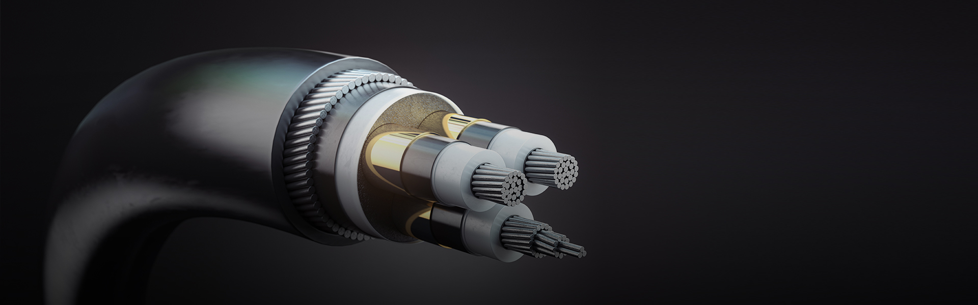
How Signal Integrity Degrades in High-Speed Computer Cables and What Construction Parameters Control It
In high-performance computer cables operating at multi-gigabit data rates, signal integrity is not a single measurable property but the aggregate result of four interdependent degradation mechanisms — attenuation, reflection, crosstalk, and mode conversion — each of which is controlled by specific construction parameters at the manufacturing stage. Understanding how each mechanism originates allows engineers to identify which cable construction attributes genuinely matter for a specific data rate and which are marketing distinctions without functional significance at the target frequency.
Attenuation increases with frequency due to the skin effect in conductors and dielectric loss in insulation, as described by the cable's insertion loss specification. At 10 Gbps (approximately 5 GHz Nyquist frequency for NRZ signaling), insertion loss over a 1-meter cable is dominated by dielectric loss if foamed polyethylene insulation is not used — solid PE has a loss tangent of approximately 0.0002, while PVC has a loss tangent 250 times higher. For cables intended to operate at 25 Gbps or above, the foaming percentage of the insulation dielectric becomes a critical manufacturing parameter: each 10% increase in foam void fraction reduces the effective dielectric constant by approximately 0.08 and reduces the loss tangent proportionally, meaningfully extending the usable cable length at a given data rate.
Reflections arise at impedance discontinuities — any point along the cable where the characteristic impedance deviates from its nominal value. The primary manufacturing source of impedance variation is insulation eccentricity: if the insulation wall is thicker on one side of the conductor than the other, the local characteristic impedance varies as the conductor pair rotates through its twist. This produces periodic impedance variation at the twist lay frequency, which generates structural return loss peaks at specific frequencies corresponding to harmonics of the lay length. A cable with 15 mm twist lay length produces a structural return loss resonance at approximately 10 GHz — directly in the operating band of 10GBase-T and PCIe Gen 4 applications. Controlling insulation eccentricity to below ±5% of nominal wall thickness, through precision die design and melt pressure stabilization in the extrusion process, is the manufacturing countermeasure against structural return loss.
USB Cable Generations and the Engineering Changes Required at Each Step Up in Performance
Each USB generation has required fundamental changes in cable construction — not just tighter tolerances on the same design. The progression from USB 2.0 to USB4 represents a 1,000-fold increase in data rate (480 Mbps to 40 Gbps), and the cable constructions required at each end of this range share almost no design features in common beyond the conductor material.
| Standard | Max Data Rate | Max Cable Length | Key Construction Requirement |
| USB 2.0 | 480 Mbps | 5 m (passive) | Single differential pair, foil shield; 90 Ω ± 15% impedance |
| USB 3.2 Gen 1 | 5 Gbps | 3 m (passive) | SuperSpeed pair added; individual pair foil shields; 90 Ω ± 7% |
| USB 3.2 Gen 2×2 | 20 Gbps | 1 m (passive) | Two TX/RX SuperSpeed pairs; tight impedance and skew control; foamed PE insulation required |
| USB4 Gen 2×2 | 20 Gbps | 0.8 m (passive) | Thunderbolt 3 compatible; active equalization chip may be embedded in connector; S/FTP construction |
| USB4 Gen 3×2 | 40 Gbps | 0.8 m passive; active required >0.8 m | Full S/FTP; active retimer ICs; intra-pair skew <3 ps/m; foamed PTFE or PE insulation |
The passive length limit for USB4 Gen 3×2 cables (40 Gbps) deserves particular attention. The 0.8-meter passive limit is not a safety specification but a signal integrity limit: beyond this length, insertion loss and inter-pair skew accumulate to a level that exceeds the equalization capability of the receiver. Cable manufacturers extending passive reach beyond 0.8 meters at 40 Gbps must embed active re-timer or linear equalizer ICs within the cable assembly — typically in one or both connector housings — that compensate for the cable's frequency-dependent attenuation. These active elements add cost, require power (drawn from the USB power delivery bus), generate heat that must be dissipated within the connector housing, and introduce latency. A cable labeled "USB4 40 Gbps 2-meter" that does not disclose its active components or does not draw power from VBUS when connected should be viewed with skepticism, as passive 40 Gbps performance at 2 meters is not achievable with any currently available conductor and insulation material combination.
Intra-Pair and Inter-Pair Skew: Why Timing Errors in Differential Pairs Limit Maximum Data Rate
Skew is the timing difference between signals that should arrive simultaneously, and in high-performance computer cables it manifests at two levels — within a differential pair (intra-pair skew) and between different pairs (inter-pair skew). Both types degrade signal integrity, but through different mechanisms, and each is controlled by different manufacturing parameters.
Intra-pair skew — the propagation delay difference between the "+" and "–" conductors of a single differential pair — arises primarily from geometric asymmetry between the two conductors. If one conductor in a pair has a fractionally larger diameter, a slightly thicker insulation wall, or is positioned systematically closer to the cable center than its partner, it experiences a slightly different propagation velocity than its partner. The propagation velocity in a cable is v = c/√(εeff), where εeff is the effective dielectric constant of the insulation surrounding the conductor — any asymmetry in the dielectric environment between the two conductors of a pair produces a propagation velocity difference and hence intra-pair skew. At 40 Gbps (25 ps UI for NRZ signaling), even 1 ps/m of intra-pair skew accumulated over a 1-meter cable occupies 4% of the unit interval, leaving very little margin for the receiver's clock and data recovery circuit to correctly sample the incoming data eye. The USB4 Gen 3×2 specification limits intra-pair skew to 3 ps/m, which requires conductor diameter matching within ±0.5% and insulation wall eccentricity below ±3% across the full cable length.
Inter-pair skew — the propagation delay difference between separate pairs carrying related signals — becomes critical in protocols that use multiple lanes in parallel, such as PCIe, HDMI 2.1, and DisplayPort 2.0. In these protocols, a multi-lane data word is split across pairs, and the receiving chip must align all lanes to reconstruct the original data. The receiver uses lane-to-lane skew compensation circuitry to compensate for inter-pair skew, but this compensation has a finite range — typically 20–64 UI for PCIe Gen 5 receivers. If the inter-pair skew in the cable assembly exceeds the receiver's compensation range, the link cannot establish, even if each individual lane has acceptable signal quality. Inter-pair skew is primarily controlled by matching the electrical length of all data pairs within the cable — ensuring that each pair has the same effective dielectric constant and physical path length. This is achieved through matched lay lengths, matched insulation dielectric constant across all pairs (requiring consistent insulation compound viscosity during extrusion), and length-matched pair routing within the cable assembly.
Active Optical Cable Technology: When and Why Copper Computer Cables Reach Their Physical Limits
Copper-based high-performance computer cables face a fundamental physical limitation: as data rates increase, the skin effect and dielectric loss increase proportionally, reducing the maximum passive cable length that can support a given data rate. For 100 Gbps and above, this limitation becomes a practical constraint at cable lengths relevant to data center rack wiring (3–5 meters) and cross-rack connections (10–30 meters). Active optical cables (AOC) — which use standard copper electrical interfaces at both ends but convert the signal to optical within the connector housing for transmission over optical fiber — bypass this limitation by using a transmission medium (light in fiber) with negligible attenuation per meter at data center distances.
The optical-to-electrical conversion in an AOC occurs at the VCSEL (vertical-cavity surface-emitting laser) driver IC in the transmitting connector and at the photodetector in the receiving connector. The copper cable between the equipment port and the VCSEL driver is typically less than 10–15 mm — short enough that copper losses are negligible regardless of data rate. This architecture allows AOCs to present a standard electrical interface (SFP+, QSFP28, QSFP-DD, or other form factors) to the host equipment while transparently extending the effective link length to 50–100 meters or beyond, depending on fiber type and optical wavelength. From the host equipment's perspective, the AOC is indistinguishable from a passive copper direct-attach cable (DAC) — no driver configuration or link-layer changes are required.
The trade-offs that govern the choice between passive copper DAC, active copper cable, and AOC in data center applications are summarized across three key dimensions:
- Length range: Passive copper DAC is optimal for 0–3 meters at 100 Gbps and 0–1 meter at 400 Gbps. Active copper cables extend passive reach to 5–7 meters at 100 Gbps. AOC supports 1–100 meters (and to 300 meters with single-mode fiber), making it the only viable option for cross-aisle and inter-rack connections at 400 Gbps and above.
- Power consumption: Passive copper DAC consumes no power in the cable assembly itself (only at the transceiver). Active copper consumes 0.5–1.5 W per end in the cable-embedded electronics. AOC consumes 1.0–3.0 W per end in the VCSEL driver and photodetector circuits. In a data center with 10,000 active links, the power difference between passive DAC and AOC can represent 20–30 kW of additional heat load requiring cooling capacity.
- Repairability and flexibility: Passive copper DAC can be reterminated in the field if a connector is damaged; the cable itself has no components that can fail independently of physical damage. AOC assemblies are non-repairable — a failed VCSEL, driver IC, or fiber splice requires replacement of the entire cable assembly. AOC cables are also more vulnerable to bend radius violations than copper cables, as fiber bend radius limits (typically 30 mm for OM3/OM4 multimode fiber) are tighter than those of copper computer cables.
PCIe Cable Specifications from Gen 3 to Gen 6: What Changes Between Generations and Why
PCI Express has evolved through six generations with data rate doubling at each step, and each generation transition has required cable construction changes to maintain signal integrity within the specification's compliance margin. Unlike network cables where the cable is the primary signal transmission medium, PCIe cables connect expansion slots or add-in cards where the cable is one segment of a longer channel including PCB traces, connectors, and vias — making the cable's insertion loss budget only a fraction of the total channel budget.
PCIe Gen 3 (8 GT/s per lane) specified a total channel insertion loss limit of 20 dB at 4 GHz (the Nyquist frequency for 8 GT/s NRZ signaling). For a cable segment within this channel, a practical allocation is 8–10 dB, allowing cable lengths of 1–2 meters with well-designed foil-shielded twisted pair construction using solid PE insulation. The encoding scheme (128b/130b) introduced at Gen 3 improved coding efficiency but did not change the Nyquist frequency relative to the line rate.
PCIe Gen 4 (16 GT/s) doubled the Nyquist frequency to 8 GHz, roughly doubling insertion loss for the same cable length because both conductor skin effect loss (proportional to √f) and dielectric loss (proportional to f) increased. To maintain cable segment insertion loss within the reduced allocation, foamed PE insulation became effectively mandatory for cables longer than 0.5 meters at Gen 4, as solid PE produces 15–20% higher insertion loss at 8 GHz than an equivalent foamed PE construction. PCIe Gen 5 (32 GT/s, 16 GHz Nyquist) pushed cable insertion loss requirements to the point where PCIe SIG released the OCuLink and PCIe Cable Specification v2.0 defining active cable requirements, acknowledging that passive cable lengths exceeding 1 meter at 32 GT/s require embedded signal conditioning to maintain compliance.
PCIe Gen 6 introduced PAM4 (4-level pulse amplitude modulation) encoding in place of NRZ, which halved the required Nyquist frequency for a given data rate (64 GT/s with PAM4 has the same 16 GHz Nyquist as 32 GT/s NRZ). This encoding change partially relieved cable insertion loss requirements, but introduced linearity requirements: PAM4 uses four signal levels instead of two, and nonlinearity in the cable's frequency response causes the eye heights at different signal levels to be unequal, reducing the noise margin for the inner eye openings. High-performance computer cables for PCIe Gen 6 must therefore meet not just insertion loss limits but also limits on group delay variation (the frequency dependence of signal propagation velocity), which introduces amplitude-to-phase distortion that disproportionately affects PAM4 performance.
Conductor Material Options for High-Speed Computer Cables: Copper Clad Aluminum and Silver-Plated Copper Compared
The conductor material in a high-performance computer cable is a more nuanced specification than it appears. Copper is the universal baseline, but two modified conductor constructions — copper clad aluminum (CCA) and silver-plated copper (SPC) — are used in specific contexts, and their performance trade-offs are poorly understood in general procurement practice.
Copper Clad Aluminum (CCA)
CCA conductors consist of an aluminum core clad with a thin outer layer of copper. The copper layer thickness is typically 10–15% of the conductor radius. CCA offers significant weight and cost reduction compared to solid copper — aluminum density is 2.7 g/cm³ versus 8.9 g/cm³ for copper, so CCA conductors are approximately 40–45% lighter per unit length. At high frequencies where the skin effect confines current to the conductor surface, CCA behaves essentially identically to solid copper: the skin depth at 1 GHz in copper is approximately 2 μm, which is far thinner than the copper cladding thickness in practical CCA conductors. For this reason, CCA is technically acceptable for high-frequency signal conductors where the current density is concentrated in the copper cladding layer. The limitation of CCA arises in DC and low-frequency applications where current penetrates the full conductor cross-section: aluminum's conductivity is approximately 61% that of copper, so CCA conductors have meaningfully higher DC resistance than solid copper of the same diameter. For the power conductors within a computer cable (USB VBUS, PCIe auxiliary power), higher DC resistance means larger voltage drop and higher I²R heating at rated current — making solid copper preferable for power conductors in the same cable where CCA data conductors may be acceptable.
Silver-Plated Copper (SPC)
Silver has slightly higher conductivity than copper (6.30 × 10⁷ S/m vs. 5.96 × 10⁷ S/m), and its superior surface characteristics — silver oxide is conductive, unlike copper oxide — make silver plating beneficial at very high frequencies where current flows in an extremely thin surface layer. The primary practical advantage of silver plating in high-frequency computer cables is not the marginal conductivity improvement but the prevention of copper oxide formation on the conductor surface. Copper oxide is a semiconductor with much lower conductivity than metallic copper; as conductor surface oxidation progresses, the effective skin depth resistance increases above the value predicted from bulk copper conductivity, causing higher insertion loss than specified for the cable. Silver plating, by providing an oxidation-resistant surface layer, maintains the conductor's surface resistance at the design value throughout the cable's service life. This benefit is most significant in cables stored for extended periods before use or operating in humid or mildly corrosive environments. For cables used immediately after manufacture in clean environments, the difference between silver-plated and bare copper conductors is measurable but typically small relative to the insertion loss specification limit.
How OEM Computer Cable Specifications Should Be Written to Prevent Performance Shortfalls in Production
Custom OEM computer cable specifications that focus exclusively on electrical parameters — impedance, insertion loss, crosstalk — without specifying the underlying construction attributes that produce those parameters create a verification problem: a cable can meet measured electrical specifications on a sample batch while using construction choices that will produce out-of-specification performance under different production conditions or after aging. A robust OEM specification defines both the measurable electrical performance parameters and the construction constraints that ensure those parameters are maintained across production batches and throughout service life.
The following construction parameters should be explicitly specified in a high-performance computer cable OEM specification, rather than left to the manufacturer's discretion:
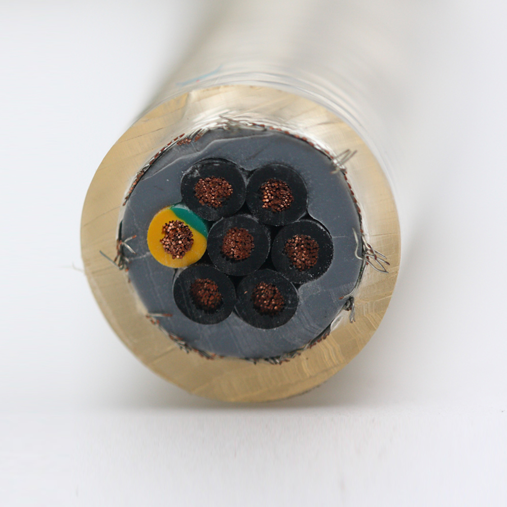
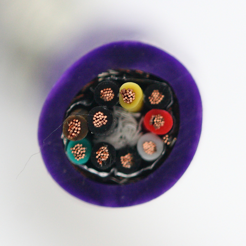
- Conductor material and stranding class: Specify solid or stranded, bare copper or silver-plated copper or CCA, and the stranding class (IEC 60228 Class 2, 5, or 6) separately for signal and power conductors within the same cable. A specification that only says "28 AWG conductor" leaves the manufacturer free to use CCA for power conductors and solid copper for signal conductors — or the reverse — without disclosure.
- Insulation material and foam percentage (if foamed): Specify the insulation polymer type (solid PE, foamed PE with minimum foam percentage, FEP, or PTFE) rather than just the nominal wall thickness. Two cables with identical insulation wall thickness but different dielectric constants (solid vs. foamed PE) will have different characteristic impedances and different insertion loss values at high frequency.
- Twist lay length range and tolerance: Specify the nominal lay length and maximum allowable deviation for each differential pair. Lay length directly controls structural return loss peak frequency and pair balance; uncontrolled lay length variation produces batch-to-batch impedance variation that can be difficult to diagnose without time-domain reflectometry testing.
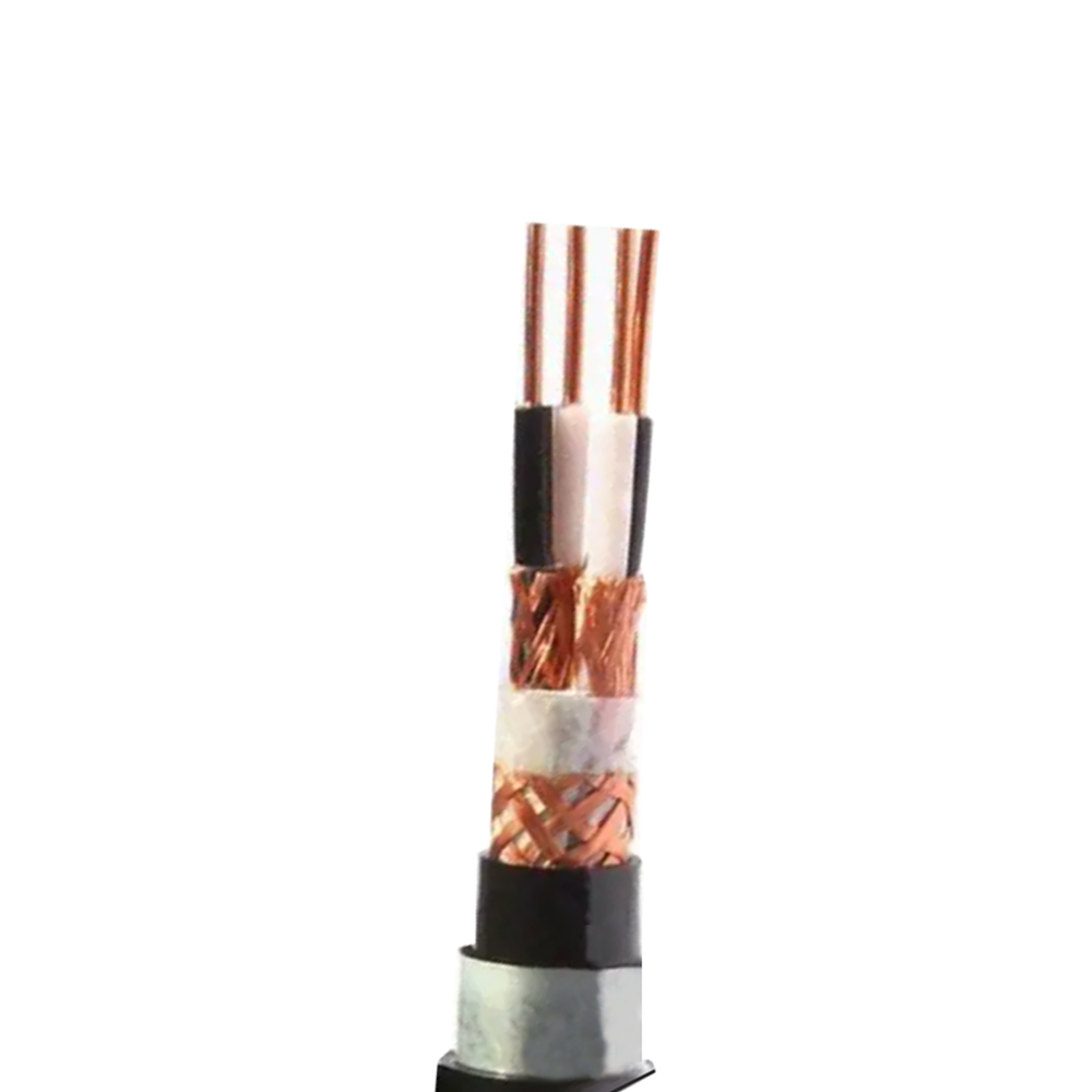
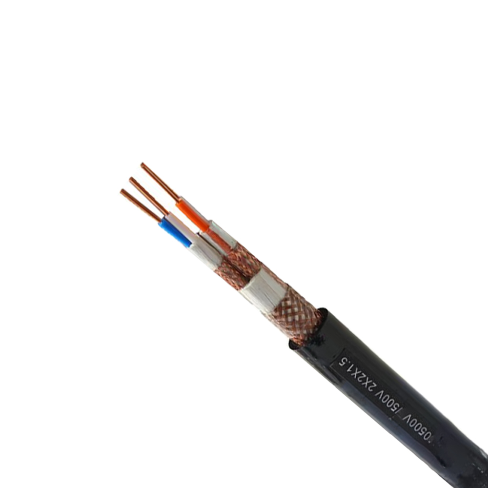
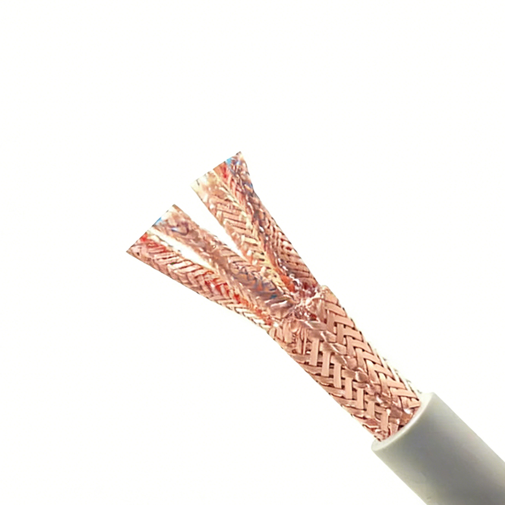
- Shield construction and coverage: Specify foil type (aluminized polyester or aluminized polypropylene), foil overlap percentage, and drain wire material for each pair shield, plus overall braid coverage percentage and wire diameter for the outer braid shield. "Fully shielded" without these details allows manufacturers to use minimal coverage constructions that technically include shielding material but provide inadequate EMI suppression at gigahertz frequencies.
- First Article Inspection (FAI) requirements: Specify which parameters must be measured on a sample from the first production run, what test equipment and procedures are to be used, and what constitutes a passing result. FAI is the contractual mechanism that prevents substitution of a lower-cost construction after sample approval. Without explicit FAI requirements in the OEM specification, the manufacturer has no contractual obligation to maintain the construction used in the approved sample across subsequent production runs.
For computer cables intended for use in products subject to regulatory certification — UL, CE, FCC Part 15 — the OEM specification should also clarify whether the cable itself must carry individual certification or whether it will be certified as a component within the end product assembly. Cable-level certification requires the specific construction to be tested and listed under the certifying body's scheme; end-product certification covers the cable as an internal component without requiring independent cable-level marks. Misalignment between what is specified and what the certification path actually requires is a common cause of project delays when regulatory review reveals that a cable specified as "UL-listed" is in fact UL-recognized only as a component, or carries UL listing for a different voltage/temperature rating than the intended application requires.