

 English
 Español
 عربى
عربى
 русский
Industry knowledge
The Chemistry Behind Halogen-Free Flame Retardancy and Why Filler Loading Is a Critical Design Variable
Conventional flame-retardant PVC cables achieve fire resistance through the release of hydrogen chloride gas during combustion, which interrupts the chemical chain reactions that sustain a flame. Halogen-free compounds cannot use this mechanism and instead rely on endothermic decomposition of metal hydroxide fillers — most commonly aluminum trihydrate (ATH, Al(OH)₃) or magnesium hydroxide (MDH, Mg(OH)₂) — to suppress combustion. When these fillers are heated to their decomposition temperature (180–200°C for ATH, 300–320°C for MDH), they release chemically bound water vapor, absorbing heat from the combustion zone and diluting the oxygen and fuel vapor concentrations in the flame. The solid residue — aluminum oxide or magnesium oxide — forms a protective char layer that insulates the underlying material from radiant heat and slows further thermal degradation.
The fundamental challenge of this flame retardancy mechanism is that achieving adequate fire performance requires extremely high filler loading — typically 50–65% by weight of the total compound formulation. At these loading levels, the metal hydroxide particles dominate the mechanical properties of the compound, significantly increasing stiffness and brittleness compared to unfilled polyolefin base polymers. An HFFR compound loaded at 60% ATH has an elongation at break of 150–200%, compared to 400–600% for the unfilled polyolefin base resin. This reduction in elongation directly affects the cable's cold temperature performance and flex life, because the insulation can crack during installation in cold environments or after extended flexing in service. Managing the mechanical-fire performance trade-off is the central formulation challenge in HFFR cable compound development, and it explains why HFFR cables from different manufacturers vary significantly in low-temperature flexibility even when they meet the same flame retardancy test standard.
MDH is preferred over ATH when the cable must operate near or above 200°C, because ATH begins to release its bound water at temperatures that overlap with normal cable operating temperatures in high-load or high-ambient conditions — causing premature filler decomposition that degrades the compound over time. MDH's higher decomposition temperature (300°C+) provides a wider margin above operating temperatures but requires higher flame temperatures to activate, meaning MDH-based compounds may show slightly lower performance on low-intensity flame tests while performing equivalently or better under high-intensity fire exposure representative of real fire scenarios. High-quality HFFR control cable manufacturers select filler type based on the cable's temperature class rather than applying a single compound across all ratings.
What Low Smoke Standards Actually Measure and How Test Chamber Results Translate to Real Evacuation Conditions
The low smoke performance of HFFR cables is quantified by IEC 61034, which measures the minimum light transmittance through smoke generated by a burning cable sample in a standardized 3m × 3m × 3m enclosed chamber. The test burns a specified length of cable on a grating at the chamber floor while measuring how much light from a photometer beam is blocked by the accumulated smoke. A minimum transmittance of 60% is the threshold for compliance — meaning that at least 60% of the photometer beam intensity reaches the detector through the smoke-filled chamber. Cables that produce heavy, opaque smoke typical of burning PVC typically achieve transmittances of 5–20%, compared to 60–95% for well-formulated HFFR constructions.
The practical significance of this test result is its relationship to evacuation visibility. Research on smoke obscuration and human navigation performance in smoke-filled spaces has established that visibility distance in smoke is proportional to the extinction coefficient of the smoke layer. A transmittance of 60% in the IEC 61034 chamber (3 meters optical path length) corresponds to an extinction coefficient of approximately 0.17 m⁻¹. At this extinction coefficient, building occupants can see approximately 10–15 meters through the smoke with illuminated exit signs visible at exit door levels — sufficient to navigate most building corridors toward exits. PVC cable smoke at 10% transmittance in the same chamber produces an extinction coefficient above 0.75 m⁻¹, reducing visibility to 2–4 meters and severely impairing exit navigation even for building occupants who are not incapacitated by toxicity.
An important limitation of the IEC 61034 test that specifiers should understand is that it measures smoke quantity from a relatively small cable sample under a controlled, low-energy ignition source. Real cable tray fires in densely filled installations generate far more smoke per unit time than the test scenario, and the absolute smoke volume scales with the amount of cable burning simultaneously. This is why the IEC 61034 result should be considered alongside the flame spread performance under IEC 60332-3 (grouped cable test) — a cable that produces low smoke per unit length but fails to self-extinguish in a grouped cable test will ultimately generate more total smoke than a marginally higher-smoke cable that self-extinguishes rapidly and limits the quantity of cable consumed by the fire.
Comparing HFFR Control Cable Performance Against Standard FR-PVC Across Key Parameters
Selecting HFFR control cables over standard flame-retardant PVC involves trade-offs across multiple performance dimensions. The decision should be based on which parameters are critical for the specific installation environment rather than on a blanket preference for one material system over the other.
| Parameter | HFFR (LSZH) | FR-PVC | Practical Impact |
| Acid Gas Emission (IEC 60754-2) | pH >4.3; conductivity <10 μS/mm | pH typically 1–2; high HCl emission | HCl corrodes electronics and metalwork throughout affected area post-fire |
| Smoke Density (IEC 61034) | ≥60% transmittance | Typically 5–25% transmittance | Critical for evacuation visibility in enclosed spaces |
| Low-Temperature Flexibility | Moderate; typically –15°C to –25°C | Good; –20°C to –40°C (plasticizer-dependent) | HFFR may crack during cold-weather installation without conditioning |
| Oil and Chemical Resistance | Variable; base polymer dependent | Good against oils; PVC swells in some solvents | Must verify compound chemical compatibility for machine tool environments |
| Insulation Resistance (at temperature) | High; stable across temperature range | Decreases significantly above 60°C due to plasticizer migration | HFFR preferred for high-temperature control panel environments |
| Relative Cost | 25–50% premium over FR-PVC | Baseline | Cost premium often justified by reduced post-fire remediation costs in electronics-rich environments |
One parameter not captured in the table above is long-term aging behavior. PVC insulation contains plasticizers — typically phthalate esters or adipate esters — that migrate out of the compound over decades of service, causing the cable jacket and insulation to become progressively stiffer and more brittle. This plasticizer migration accelerates at elevated temperatures and is irreversible; a PVC cable that is flexible at installation may be severely embrittled after 20 years in a warm control panel. HFFR compounds based on polyolefin resins do not contain plasticizers and do not experience this aging mechanism, maintaining their mechanical properties throughout service life. For control cables in critical infrastructure applications with design service lives of 25–40 years, this aging difference is a significant factor favoring HFFR constructions even in environments where fire performance requirements alone might not mandate it.
Circuit Integrity Under Fire: How HFFR Cables with Fire Resistance Differ from Standard LSZH
Low smoke halogen-free cables and fire-resistant cables address different fire safety objectives and are frequently confused in specifications. Standard HFFR/LSZH cables limit the toxicity and opacity of combustion products, but they do not guarantee that the cable will continue to carry signal or power during the fire itself — the cable will eventually fail as insulation degrades. Fire-resistant cables (tested to IEC 60331) are designed to maintain electrical circuit integrity at specified temperatures for defined durations, enabling the systems they serve — emergency lighting, fire alarm, smoke extraction fans, emergency power — to continue operating while the building is being evacuated.
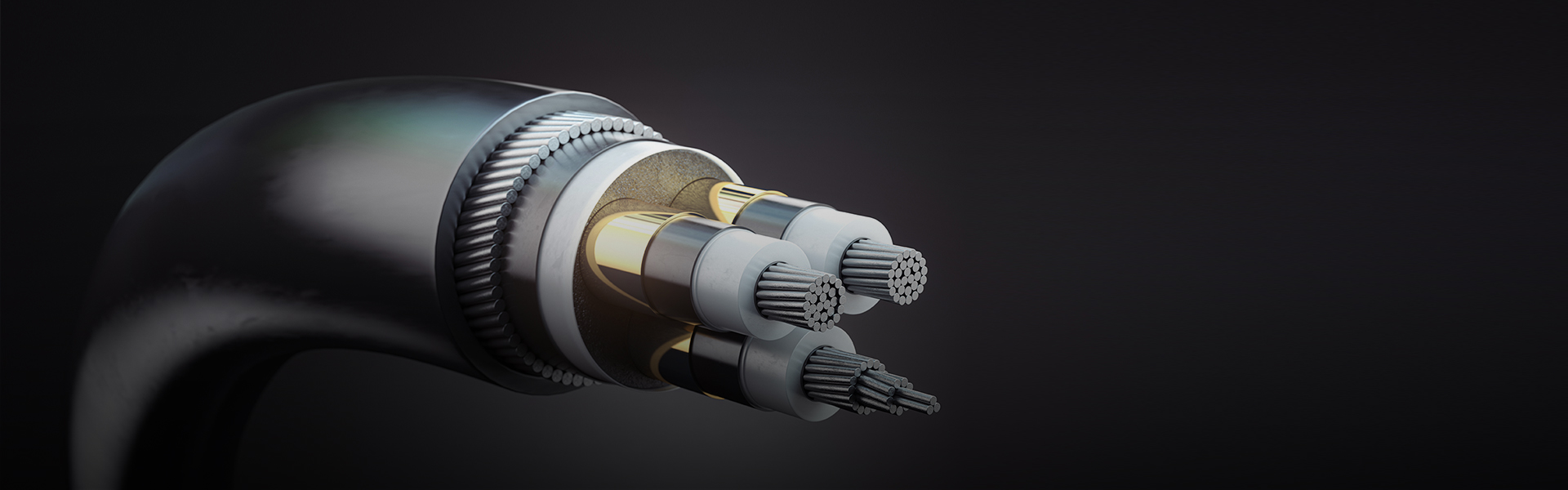
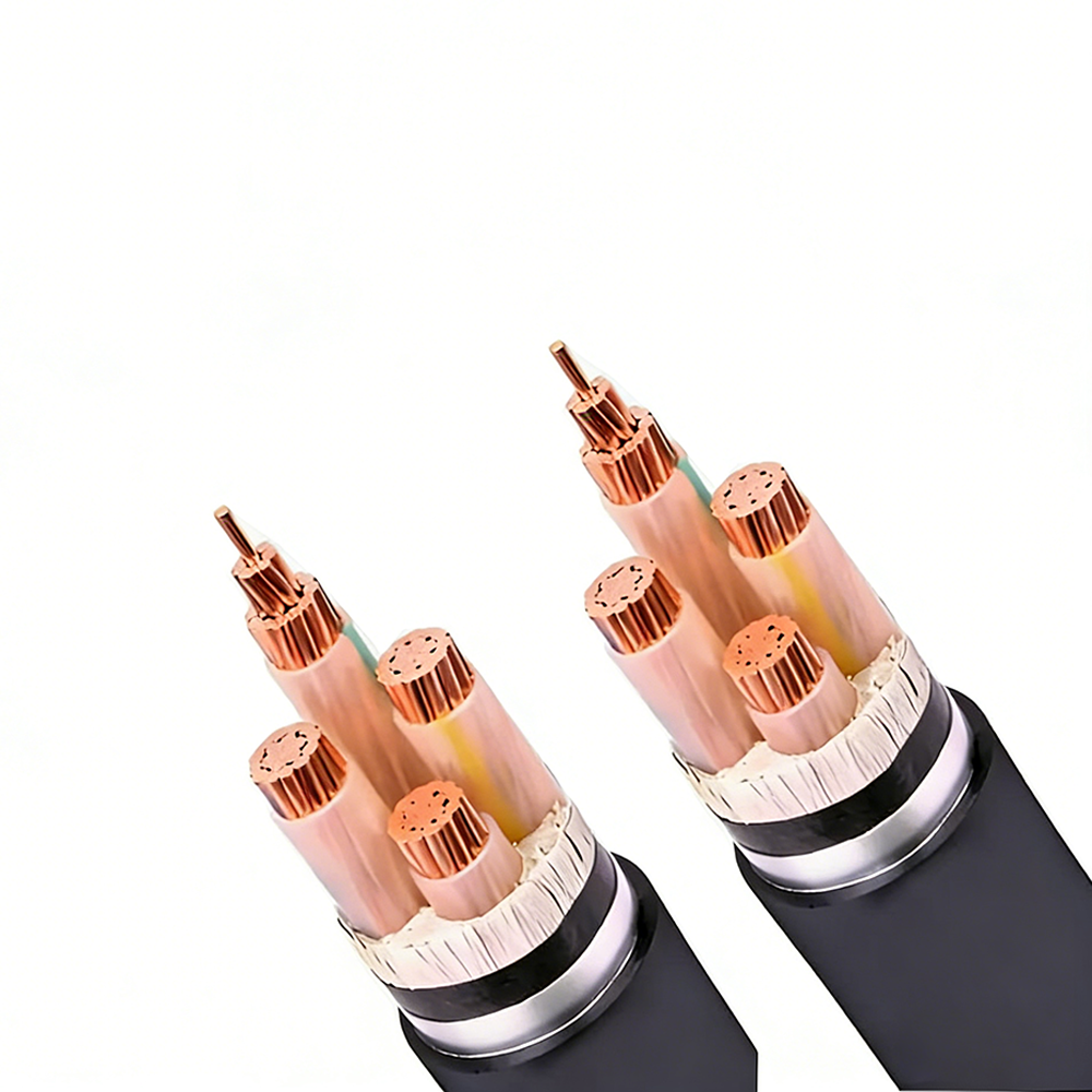
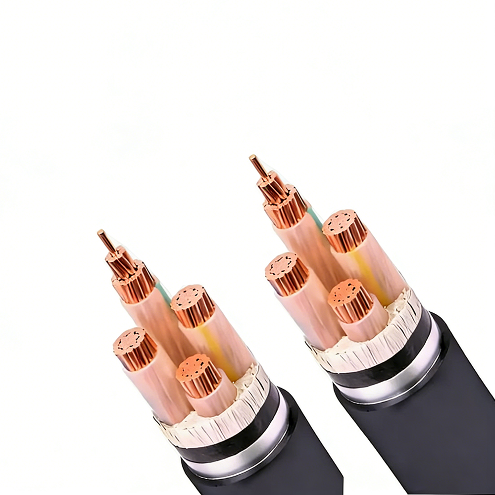
IEC 60331 subjects completed cable samples to direct flame at 750°C (IEC 60331-21 for wire and small cables) or 830°C (IEC 60331-23 for cables with a larger cross-section) while the cable remains under rated electrical load. The cable must maintain continuity for the test duration — typically 90 or 180 minutes — without flashover, short circuit, or open circuit. Achieving this performance requires a fundamentally different insulation system from standard HFFR: a mica tape layer wrapped around each conductor or around the cable core provides a refractory mineral insulation barrier that remains electrically intact at flame temperatures where all organic polymer materials have long since combusted.
The combination of fire resistance and halogen-free performance — specified as HFFR + CWZ (circuit-integrity under fire) in some standards, or designated by EN 50200/EN 50362 in European railway and public building applications — is achieved by layering mica tape circuit integrity with an outer HFFR jacket that limits combustion products. This construction is mandatory for emergency control cables in hospitals, tunnels, high-rise buildings, and offshore platforms under a range of national and international fire safety codes. The mica tape layer adds significant cost and increases cable diameter (typically 15–25% larger OD than an equivalent standard HFFR cable), but it is the only construction that satisfies both fire product toxicity requirements and circuit survival requirements simultaneously.
A practical installation consideration for fire-resistant HFFR control cables is that the mica tape layer beneath the insulation is mechanically fragile — mica is a brittle mineral that can delaminate if the cable is bent below its minimum bend radius or subjected to impact during installation. Damaged mica tape may not be visible externally if the outer insulation remains intact, but the circuit integrity performance will be compromised at the damage location. Fire-resistant cables must be handled with greater care than standard control cables during installation, with strict adherence to minimum bend radius specifications and protection from impact in cable tray and conduit environments.
Specifying HFFR Control Cables for Specific Industry Environments: Key Differences in Requirements
HFFR control cables are required across several industry sectors, but the specific performance thresholds, test standards, and construction requirements vary significantly between sectors. A cable certified for one sector may not satisfy the requirements of another even if its material system is identical. The following breakdown covers the most common high-demand sectors where halogen-free low smoke control cables are specified:
Rail and Mass Transit
Railway applications are governed by EN 45545-2 in Europe, which classifies cables into hazard levels (HL1, HL2, HL3) based on the fire risk of the installation location — HL3 applies to cables in areas where passengers are present and evacuation is difficult, such as underground rail. EN 45545-2 specifies limit values for heat release rate (measured by cone calorimeter per ISO 5660), flame spread, smoke production, and toxicity index simultaneously, and the thresholds are significantly more stringent than the IEC 60332/60754/61034 suite used in building applications. In particular, the toxicity index (measured by the NF X70-100 or FTIR methods) must be below defined limits for multiple combustion gas species — CO, HCN, HF, SO₂, NOₓ, and others — not just the bulk acid gas measurement of IEC 60754. A cable meeting standard LSZH requirements for building installation may fail EN 45545-2 HL2 on toxicity index.
Marine and Offshore
Offshore platforms and commercial vessels apply IEC 60092-359 (marine cables, halogen-free) in conjunction with IEC 60331 fire resistance requirements. Marine installations add a seawater resistance requirement not present in building or rail specifications: the cable jacket must maintain its mechanical integrity after immersion and must not swell or delaminate when exposed to saltwater — relevant for cables routed through wet areas or on exposed decks. Additionally, IMO Resolution MSC.61(67) (FTP Code) specifies surface flame spread and smoke density tests conducted under the specific airflow and heat exposure conditions representative of ship compartment fires, which differ from the still-air conditions of the IEC 61034 smoke test. A cable compliant with IEC 61034 does not automatically comply with IMO FTP Code Annex 1 or 2 smoke tests without separate verification.
Industrial Automation and Intelligent Manufacturing
In industrial automation environments, HFFR control cables are increasingly specified not because local fire codes mandate them but because of the post-fire remediation cost economics. A fire involving standard PVC cables in a modern automation facility — where control panels, servo drives, PLCs, and HMI equipment represent millions of euros of investment — releases sufficient HCl to corrode electronic assemblies throughout the entire building envelope, not just the area directly affected by flames. The corrosion may not manifest as immediate failures but appears as progressive connection degradation, PCB trace corrosion, and contact resistance increases over the 6–18 months following the fire event. Replacing or cleaning HCl-contaminated electronic equipment in a large automated facility can cost 10–50 times the value of the cables that burned. This economic argument drives voluntary adoption of HFFR control cables in intelligent manufacturing facilities where no mandatory code requirement exists, and it is the basis for including HFFR cable specifications in insurance risk assessments for high-value electronic manufacturing plants.
Low-Temperature Installation of HFFR Control Cables: Risks and Conditioning Requirements
One of the most consistent field failure modes for HFFR control cables is insulation cracking during installation in cold environments, caused by the reduced elongation at break of high-filler-loading HFFR compounds at low temperatures. While standard PVC cables retain useful flexibility down to –20°C or lower due to their plasticizer content, many HFFR formulations become noticeably stiffer below 0°C and can crack if bent or uncoiled below –5°C to –10°C without precautions. This is particularly problematic in outdoor installation projects during winter months and in refrigerated facilities where cables must be routed at or below 0°C ambient temperature.
The low-temperature performance of an HFFR cable is characterized by the cold bend test (IEC 60811-504) and the cold impact test (IEC 60811-506). The cold bend test wraps the cable around a mandrel of specified diameter at a defined low temperature and checks for cracking; the cold impact test drops a weighted hammer on a cable section at low temperature and examines the insulation for cracks. These tests are conducted at the temperature claimed in the cable specification — typically –15°C, –20°C, or –25°C depending on the compound formulation. However, passing the cold bend test at –20°C does not mean the cable can be freely handled and routed at –20°C on site: the test applies a controlled bend with a defined radius and rate, while site installation involves repeated bending, pulling around corners, and coil unrolling that generates stress concentrations the test does not replicate.
The most effective mitigation for cold-weather installation of HFFR control cables is thermal conditioning: storing cable reels in a heated space at a minimum of +15°C for at least 24 hours before installation in cold environments. The thermal mass of a full cable reel means the core of the reel may remain cold for several hours after the outer layers have warmed, so conditioning time should be based on reel size — small reels (under 50 kg) may be adequately conditioned in 12 hours, while large drums (over 300 kg) may require 48–72 hours of conditioning. During installation in cold conditions, the unrolled cable should be installed promptly rather than left on the ground where it will re-cool, and bending at temperatures below the compound's rated cold bend temperature should be avoided by routing the cable in straight runs as much as possible until it reaches its final position. Manufacturers of high-quality HFFR cables increasingly publish specific cold-installation guidance alongside their standard technical datasheets, recognizing that proper installation procedure is part of the product's performance specification.
How HFFR Control Cable Certification Should Be Verified and What Documentation to Request
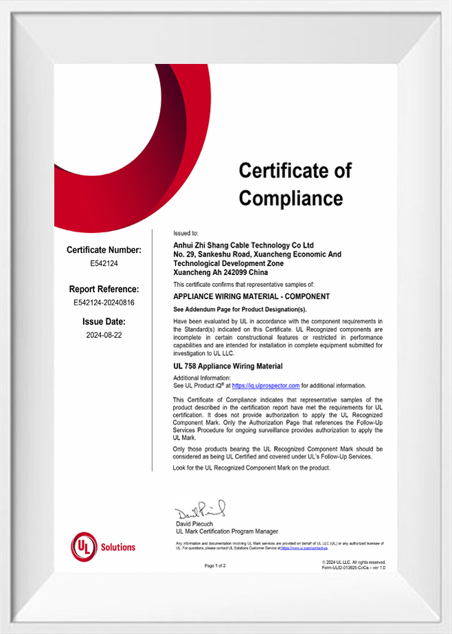
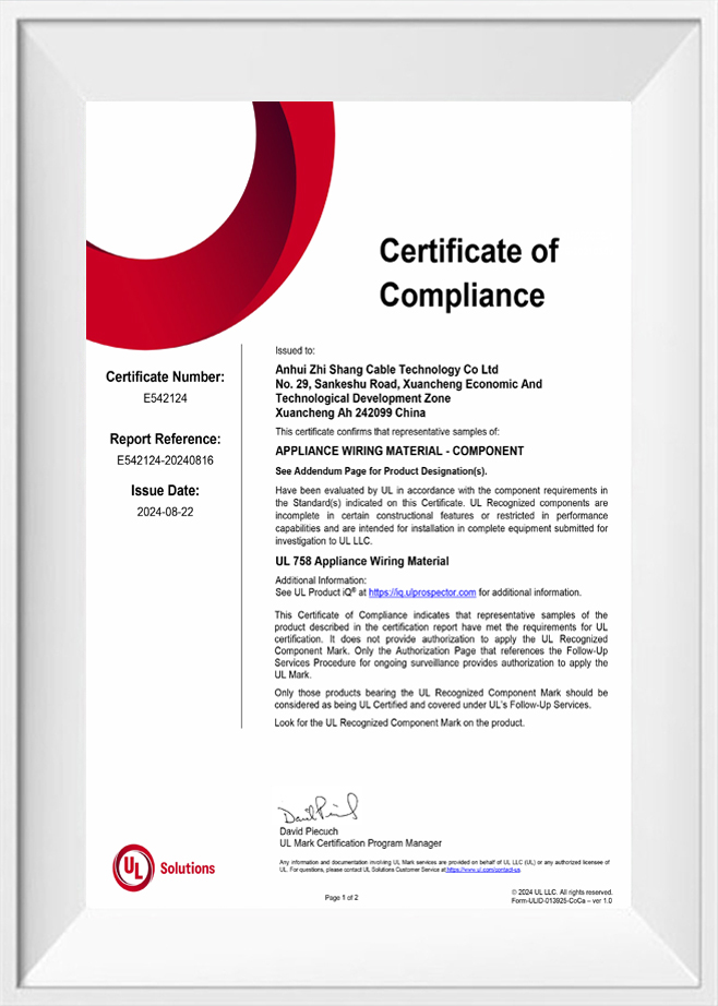
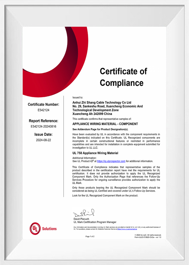
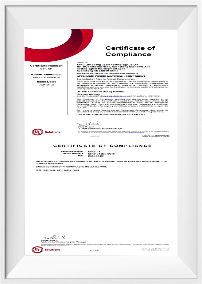
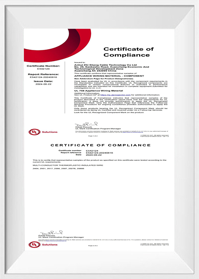
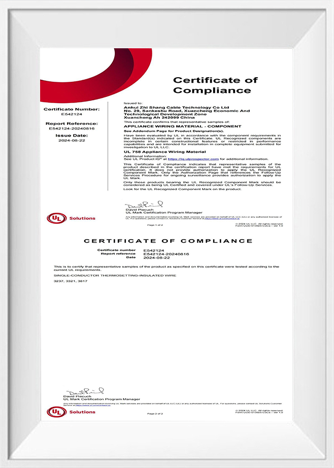
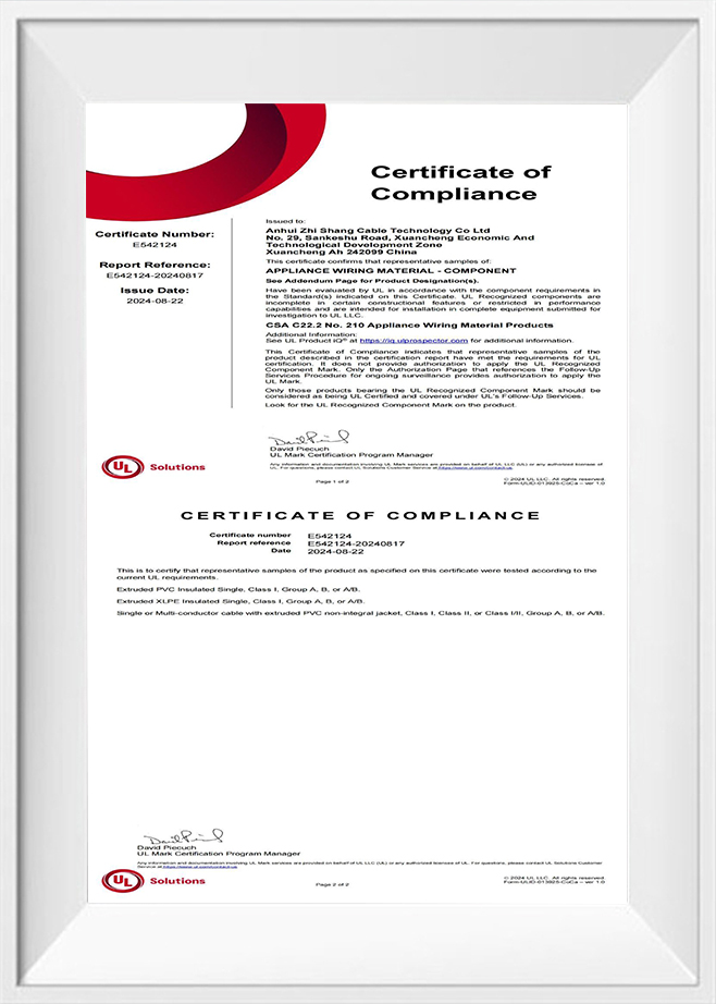
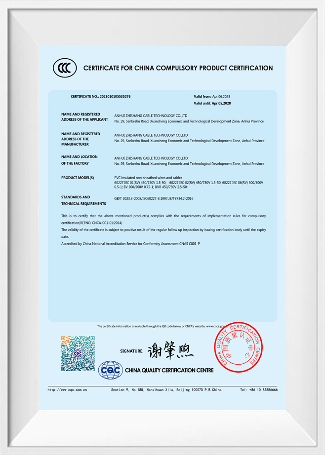
The halogen-free and low smoke claims on HFFR control cables are self-declarations unless supported by third-party test reports from accredited laboratories. Unlike some electrical safety certifications that require ongoing factory surveillance and product re-testing, HFFR fire performance certification is often obtained once for a reference construction and then applied to the full range of cable constructions made with nominally the same compound. This practice creates a meaningful verification gap: the compound formulation may be identical across all constructions, but the cable's overall fire performance depends also on the jacket wall thickness, the total polymer mass per meter (which determines total fuel load and hence smoke generation), and the stranding geometry (which affects how readily air reaches the cable core during combustion). A test report for a 4-core 1.5 mm² construction does not automatically validate the fire performance of a 12-core 2.5 mm² construction in the same cable family.
When procuring HFFR control cables for projects with formal fire safety requirements, the following documentation should be requested and verified before accepting material on site:
- IEC 60754-1 and -2 test reports: Confirming halogen content below the threshold values (pH >4.3 and conductivity <10 μS/mm for IEC 60754-2) for the specific insulation and jacket compounds used. The report should identify the laboratory, test date, and the specific material compound designation tested — not just the cable type designation.
- IEC 61034-2 smoke density test report: Confirming ≥60% transmittance for a cable construction with comparable total polymer mass per meter to the construction being purchased. If the ordered cable has significantly more polymer mass per meter (more cores, thicker jacket) than the tested construction, the actual smoke performance may be worse than the test result indicates.
- IEC 60332-3 grouped flame spread report: Specifying which category (A, B, C, or D) the tested construction meets, and the installed cable volume per meter used in the test. Category A (7 liters/m) is the most demanding and most relevant for densely filled cable trays in industrial control applications.
- Material traceability statement: A declaration from the manufacturer that the specific production batch supplied was manufactured using the same compound formulations as those used for the certification tests, including compound batch numbers where project quality documentation requirements demand this level of traceability.
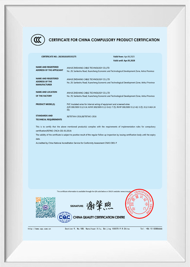
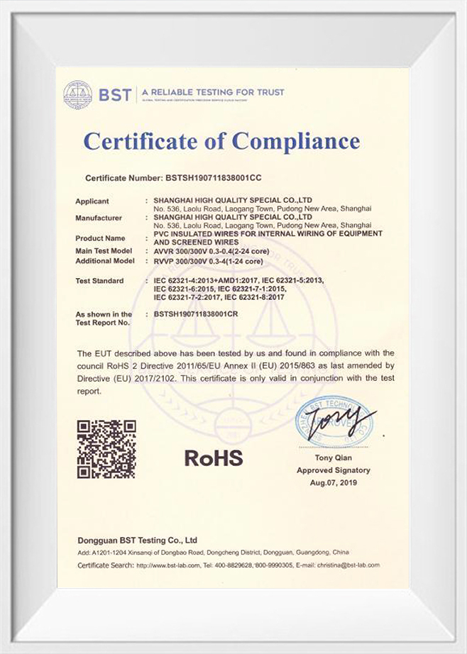
- RoHS compliance declaration: Confirming that the cable materials — including all plasticizers, stabilizers, pigments, and processing aids in the HFFR compound — comply with EU Directive 2011/65/EU substance restrictions. Some HFFR compounds use processing aids or stabilizers that contain restricted phthalates; RoHS compliance for HFFR cables is not automatic and must be verified independently of the halogen-free declaration.
For projects governed by specific regional or sector standards — EN 45545-2 for rail, IEC 60092-359 for marine, or national building codes that reference CPR (Construction Products Regulation) performance classifications in Europe — the applicable standard's specific test reports must be obtained separately from the generic IEC 60332/60754/61034 suite, as the test methods and limit values differ between standards in ways that make cross-standard compliance assumptions unreliable.