

 English
 Español
 عربى
عربى
 русский










Industry knowledge
Why Flex-Fatigue Life Is the Most Critical Performance Metric for Traveling Cables
Unlike fixed-installation cables, elevator traveling flat cables undergo continuous cyclic bending throughout their service life. Every time the elevator car moves, the cable hangs in a catenary loop that shifts position, flexing the cable repeatedly at the suspension point and along the hanging section. In a high-rise building where an elevator completes 200 to 400 trips per day, a traveling cable can accumulate millions of flex cycles over a 15- to 25-year service life. This makes flex-fatigue resistance — not tensile strength or insulation dielectric properties alone — the defining performance criterion during cable specification and procurement.
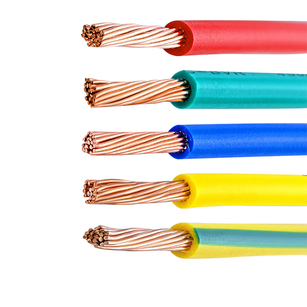
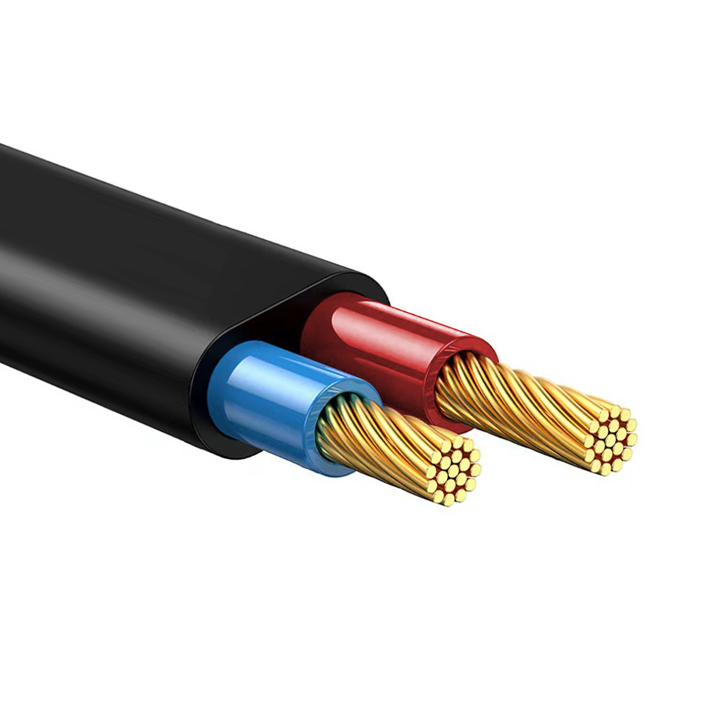
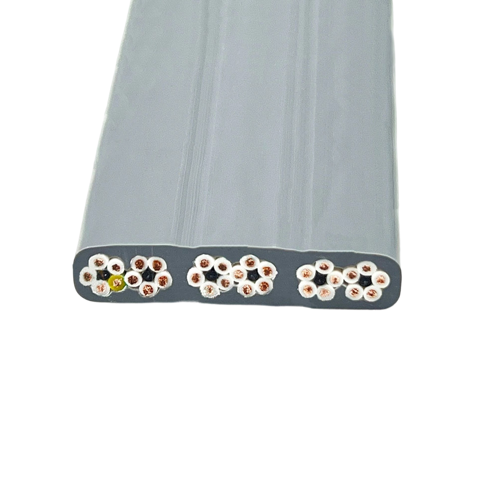
Flex-fatigue life is primarily determined by conductor strand construction. Traveling flat cables use finely stranded conductors, typically Class 5 or Class 6 per IEC 60228, which consist of a large number of very thin individual wires twisted together. A Class 6 conductor of 0.75 mm² cross-section may be constructed from over 200 individual wires each less than 0.08 mm in diameter, compared to a Class 2 rigid conductor of the same cross-section using only 7 wires. This fine stranding distributes bending stress across a much larger number of wire interfaces, dramatically extending the number of flex cycles the conductor can withstand before individual wires begin to fracture. When fine-stranded conductors are replaced with coarser alternatives to reduce cost, flex life drops sharply — often by an order of magnitude — while the cable may still pass static electrical tests, making the degradation invisible until field failures begin.
Insulation material also contributes to flex endurance. Thermoplastic elastomers (TPE) and specially formulated PVC compounds used in elevator traveling cables are engineered to remain flexible across wide temperature ranges without cracking or hardening. Standard general-purpose PVC becomes brittle at low temperatures and softens excessively at elevated temperatures, both of which accelerate insulation fatigue at the bend points. Anhui Zhishang Cable Technology Co., Ltd. qualifies insulation compounds specifically for dynamic flex applications, verifying performance through standardized bend-cycle testing rather than relying solely on material datasheets.
Flat Cable Geometry and How It Controls Loop Behavior in the Hoistway
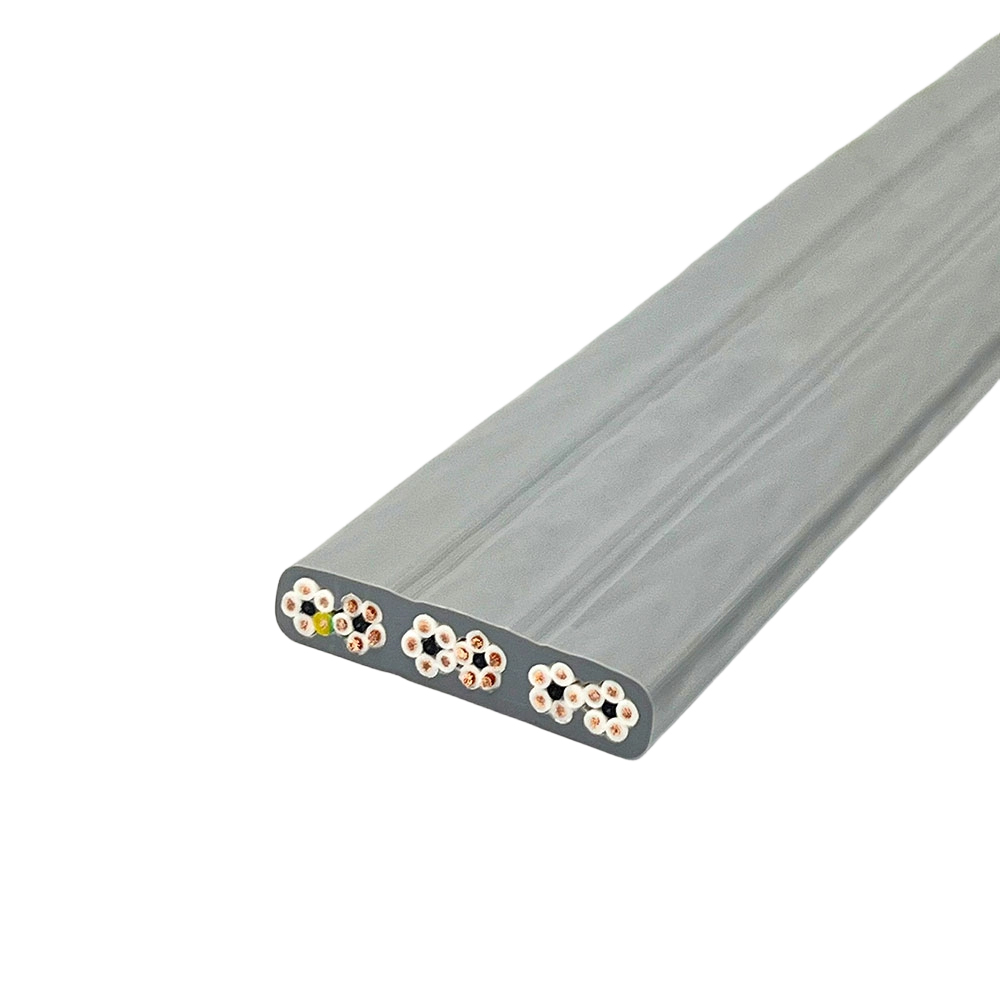
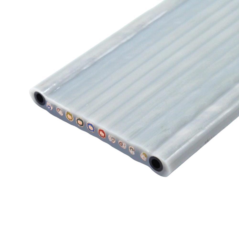
The flat cross-section of an elevator traveling cable is not simply a packaging convenience — it is a deliberate geometric choice that governs how the cable hangs, bends, and moves within the hoistway. A flat cable bends preferentially in one plane (across its narrow dimension), which keeps the catenary loop stable and predictable as the elevator travels. This controlled bending axis prevents the cable from twisting, spiraling, or forming irregular loops that could cause it to contact the hoistway walls, counterweight, or other cables — all of which are failure modes that round traveling cables are more susceptible to over time.
The width-to-thickness ratio of the flat cable directly affects the stiffness ratio between the bending and torsional axes. A cable that is too thin relative to its width becomes excessively flexible in the torsional direction, allowing it to twist under the influence of asymmetric loading or air currents in tall hoistways. Conversely, a cable that is too thick relative to its width increases bending stiffness in the preferred flex plane, which raises stress at the suspension clamp and can cause premature conductor fatigue near the attachment point. Cable manufacturers must balance these competing requirements through cross-section design, and published dimensional specifications should be evaluated with this functional context in mind rather than treated as arbitrary physical characteristics.
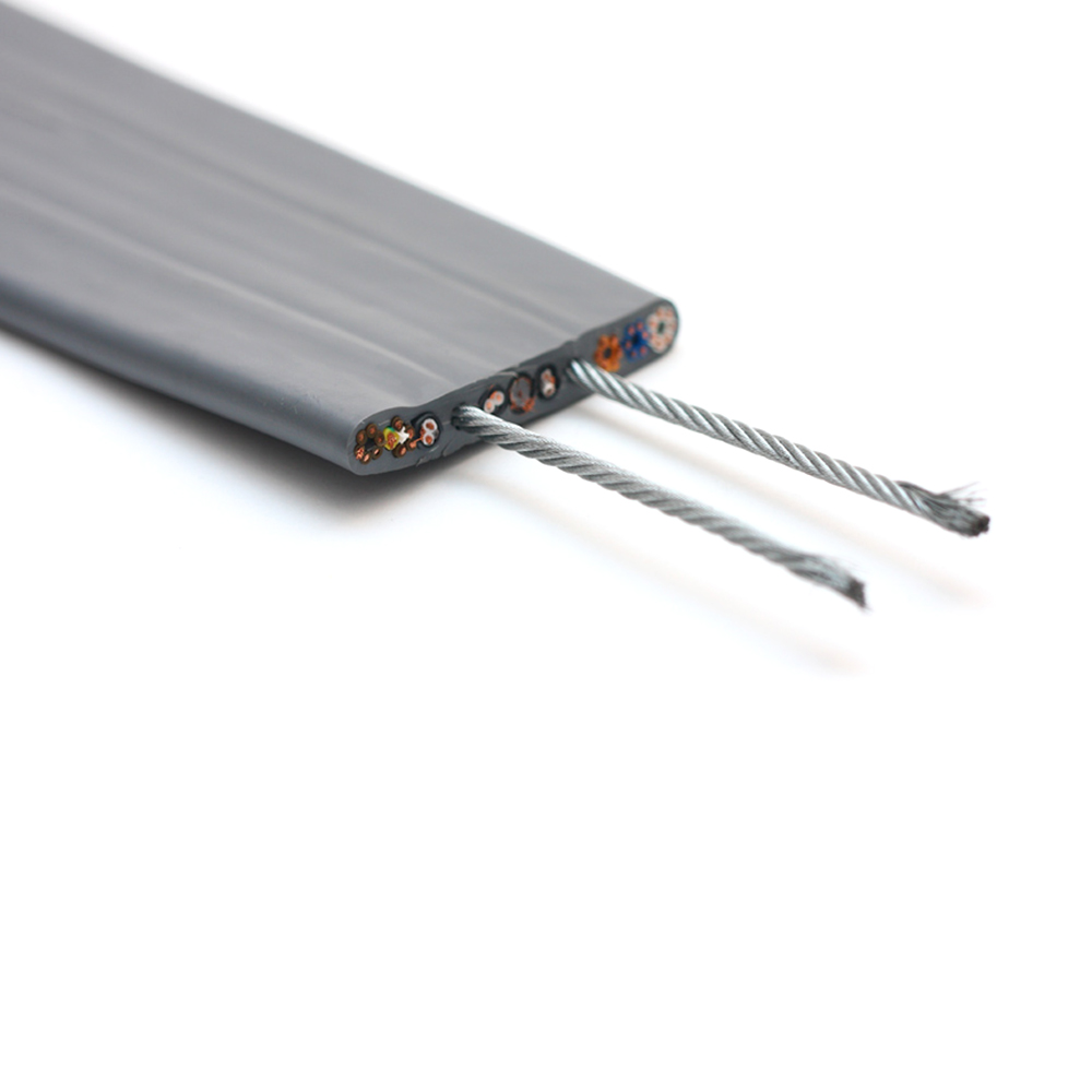
For high-rise installations exceeding 100 meters of travel, additional measures are typically required to manage loop dynamics. Steel or fiber reinforcing elements are sometimes embedded within the flat cable parallel to the conductors, providing controlled longitudinal stiffness that prevents excessive loop sag while maintaining transverse flexibility. The position of these reinforcing elements within the cable cross-section affects bending neutrality — ideally, they should be placed at or near the neutral bending axis so they carry tensile and compressive loads during hanging without adding to the bending stress experienced by the conductors alongside them.
Key Geometric Parameters That Affect Hoistway Loop Stability
- Width-to-thickness ratio: Determines the ratio of bending to torsional stiffness; governs whether the cable maintains a stable single-plane loop or tends to twist.
- Suspension midpoint position: The loop attachment point relative to cable length affects loop geometry at different car positions; incorrect midpoint selection causes the cable to drag on the pit floor at low positions or pull taut at the top of travel.
- Reinforcing element placement: Steel or Kevlar fillers add longitudinal stiffness; their distance from the neutral axis must be minimized to avoid amplifying bending stress in adjacent conductors.
- Cable weight per meter: Heavier cables produce greater catenary sag and higher tensile loads at the suspension clamp; for long travel distances, weight management is as important as electrical capacity.
Circuit Composition in Modern Elevator Traveling Cables: Beyond Simple Power and Control
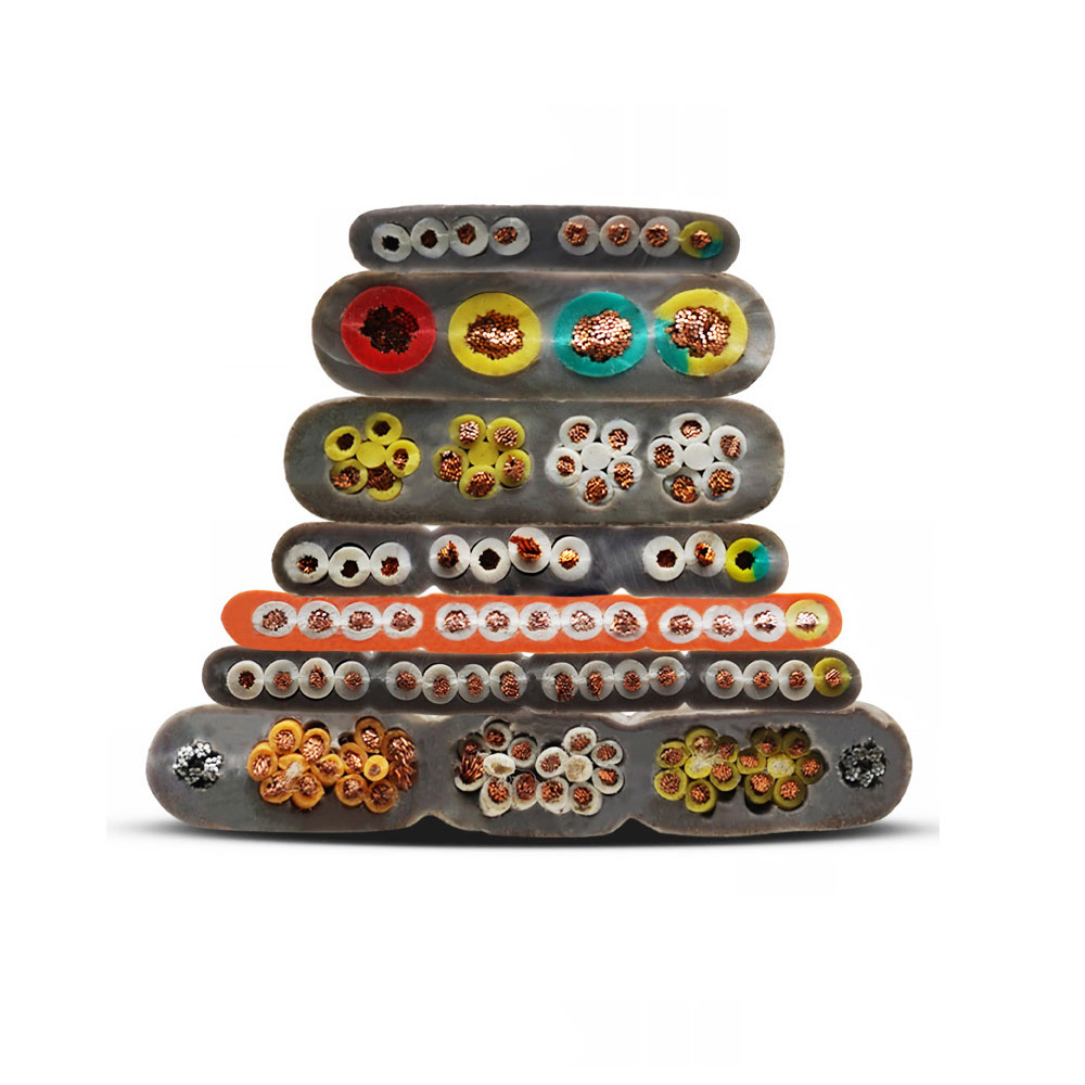
Contemporary elevator systems require traveling cables to carry an increasingly diverse mix of circuit types within a single flat cable body. Early installations used separate cables for power and control, but modern integrated flat cables combine power conductors, control signal pairs, communication data pairs, and in some cases coaxial elements for video or high-frequency signaling — all within one cable that must maintain electrical isolation between circuit types while flexing millions of times. Understanding what each circuit type requires in terms of conductor sizing, shielding, and isolation is essential for evaluating whether a cable specification matches the actual system demands.
| Circuit Type | Typical Conductor Size | Shielding Required | Primary Function |
|---|---|---|---|
| Power supply (lighting / fan) | 1.0 – 2.5 mm² | No | Car lighting, ventilation, door motors |
| Safety / control circuits | 0.75 – 1.5 mm² | Optional | Safety chain, floor selection, door control |
| Serial communication (CAN / RS485) | 0.5 – 0.75 mm² twisted pair | Yes (individual or overall) | Controller-to-car data bus |
| Video / intercom | Coaxial or shielded pair | Yes (coaxial shield) | CCTV, passenger intercom |
| Earthing / PE conductor | Equal to largest power core | N/A | Protective earthing of car metalwork |
Shielding within a flat traveling cable presents a particular engineering challenge because conventional braided or foil shields reduce flexibility and add weight. Individual pair shielding using aluminized polyester tape with a drain wire is the practical solution for data and communication pairs within a traveling cable — it provides adequate EMI attenuation without significantly stiffening the cable or increasing its cross-section. Overall shielding of the entire cable bundle is less common in traveling cable applications because it would create a rigid element running the full cable width, degrading bend performance. As Zhishang Cable has found through production experience, the positioning of shielded pairs within the flat cable cross-section also matters: placing them at the center of the flat profile rather than at the edges reduces the bending strain they experience and extends shield integrity over the cable's service life.
Suspension Clamp Design and Installation Practices That Determine Long-Term Reliability
The suspension clamp — the hardware that attaches the traveling cable to the elevator car and to the hoistway midpoint bracket — is the single location where the cable transitions from a hanging dynamic element to a fixed attachment point. This transition creates a stress concentration that accounts for a disproportionate share of traveling cable failures. Poor clamp design or incorrect installation practice at this point can cause conductor fatigue, insulation abrasion, and jacket cracking within a fraction of the cable's designed service life, regardless of how well the cable itself is manufactured.
A properly designed suspension clamp distributes clamping force evenly across the full cable width without pinching individual conductor groups. Clamps that apply point loads or uneven pressure create localized bending amplification — the cable flexes sharply at the clamp edge rather than gradually transitioning to the hanging section. This dramatically accelerates conductor fatigue at the clamped section. The clamp should also provide a controlled bend radius at the cable exit point, guiding the cable into its free-hanging catenary rather than allowing it to exit at a sharp angle. Many commercially available clamps include a formed radius or strain-relief boot for this purpose; installations that use improvised clamping hardware without this feature are a common source of premature failure.
Installation length and midpoint positioning are equally consequential. The cable's free-hanging loop must be sized so that at the lowest car position, a minimum slack loop remains without the cable touching the pit floor; and at the highest car position, the loop does not become so tight that it pulls the cable under longitudinal tension. Manufacturers typically provide travel-distance-to-cable-length calculation guidelines, but these must account for the actual hoistway geometry, the position of the mid-hoistway bracket relative to the car's travel range, and any offset between the car attachment point and the hoistway bracket. Errors in any of these parameters translate directly into abnormal stress patterns that shorten cable life, making pre-installation calculation a necessary step rather than an optional refinement.