
Get more content that can help you
Content
Medium-voltage and low-voltage aerial insulated cables have become the standard solution for utilities and industrial facilities that need to deliver electricity overhead while minimizing the risks associated with bare conductors. Unlike traditional open-wire lines, these cables are covered with layers of insulation and protective sheathing, which reduces the chance of short circuits caused by tree contact, bird interference, or accidental contact with nearby structures. This makes them particularly valuable in areas with dense vegetation, urban congestion, or unpredictable weather patterns where conventional bare conductors would require constant clearance maintenance.
The shift toward insulated aerial cables reflects a broader industry trend toward reducing outage frequency and improving public safety along overhead corridors. Utilities that previously relied on bare aluminum conductors are increasingly retrofitting distribution lines with insulated alternatives, particularly in regions prone to wildfires, ice storms, or heavy storm damage, where a fallen bare wire poses a far greater hazard than an insulated one.
Although both cable types serve overhead distribution networks, they are engineered for different voltage ranges and applications. Medium-voltage aerial insulated cables typically operate between 1kV and 35kV and are used for primary distribution lines that carry power from substations to local transformers. Low-voltage aerial insulated cables generally operate below 1kV and are used for the final stretch of the network, delivering power directly to homes, businesses, and street lighting systems.
Medium-voltage cables require thicker, more robust insulation layers to withstand higher electrical stress and to prevent partial discharge, a phenomenon that can gradually degrade insulation and lead to premature failure. Low-voltage cables, while still insulated for safety, do not need the same level of dielectric strength, which allows them to be lighter and more flexible for installation on shorter spans or residential service drops.
Medium-voltage aerial cables are commonly deployed along main distribution feeders, rural electrification projects, and industrial campuses where longer spans between poles are necessary. Low-voltage aerial cables are more often found in residential subdivisions, commercial parking areas, and secondary service connections where shorter runs and easier handling are priorities.
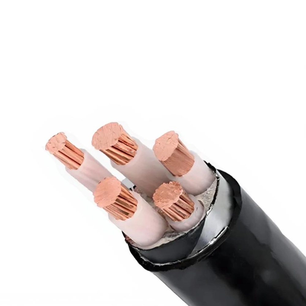
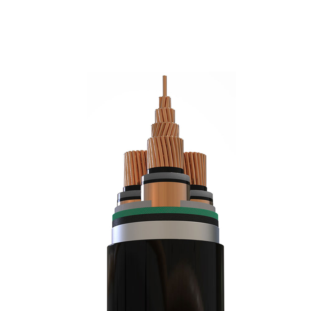
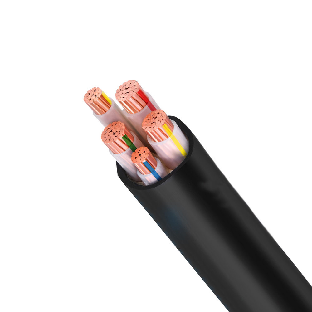
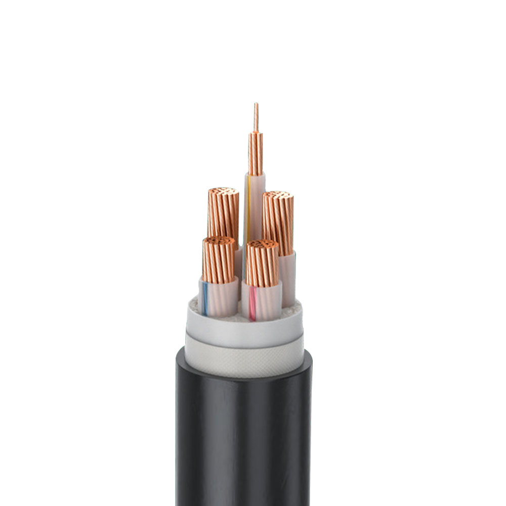
The performance and lifespan of an aerial insulated cable depend heavily on its internal construction. Understanding these layers helps engineers and procurement teams select the right product for their specific environmental and load conditions.
| Component | Function | Common Material |
| Conductor | Carries electrical current | Aluminum or copper |
| Conductor Shield | Smooths electrical field, reduces stress points | Semi-conductive compound |
| Insulation Layer | Prevents current leakage and contact hazards | XLPE or HDPE |
| Outer Jacket | Protects against UV, abrasion, and weather | Weather-resistant PE or PVC |
| Messenger Wire | Provides mechanical support along spans | Steel or aluminum alloy |
One of the strongest arguments for switching to insulated aerial cables is the significant reduction in safety incidents along the line route. Bare conductors present a continuous shock and fire hazard whenever they come into contact with tree branches, ladders, construction equipment, or wildlife. Insulated cables dramatically reduce this risk because the outer covering acts as a physical barrier between the live conductor and any incidental contact.
These safety benefits translate directly into lower liability exposure for utilities and reduced insurance costs for facilities that operate their own distribution networks, making the higher upfront material cost easier to justify over the life of the asset.
Aerial insulated cables perform particularly well in regions where vegetation management is difficult or expensive. In forested or mountainous areas, utilities can often reduce the width of required vegetation clearance corridors because insulated cables tolerate occasional branch contact without immediately faulting. This allows for narrower right-of-way clearing, which lowers both maintenance costs and environmental disturbance to surrounding ecosystems.
In coastal or industrial areas with high pollution or salt exposure, the outer jacket material can be specified with additional UV and chemical resistance to extend service life. This adaptability makes insulated aerial cables suitable for a wide range of climates, from arid desert installations to humid tropical regions where insulation degradation from moisture is a persistent concern.
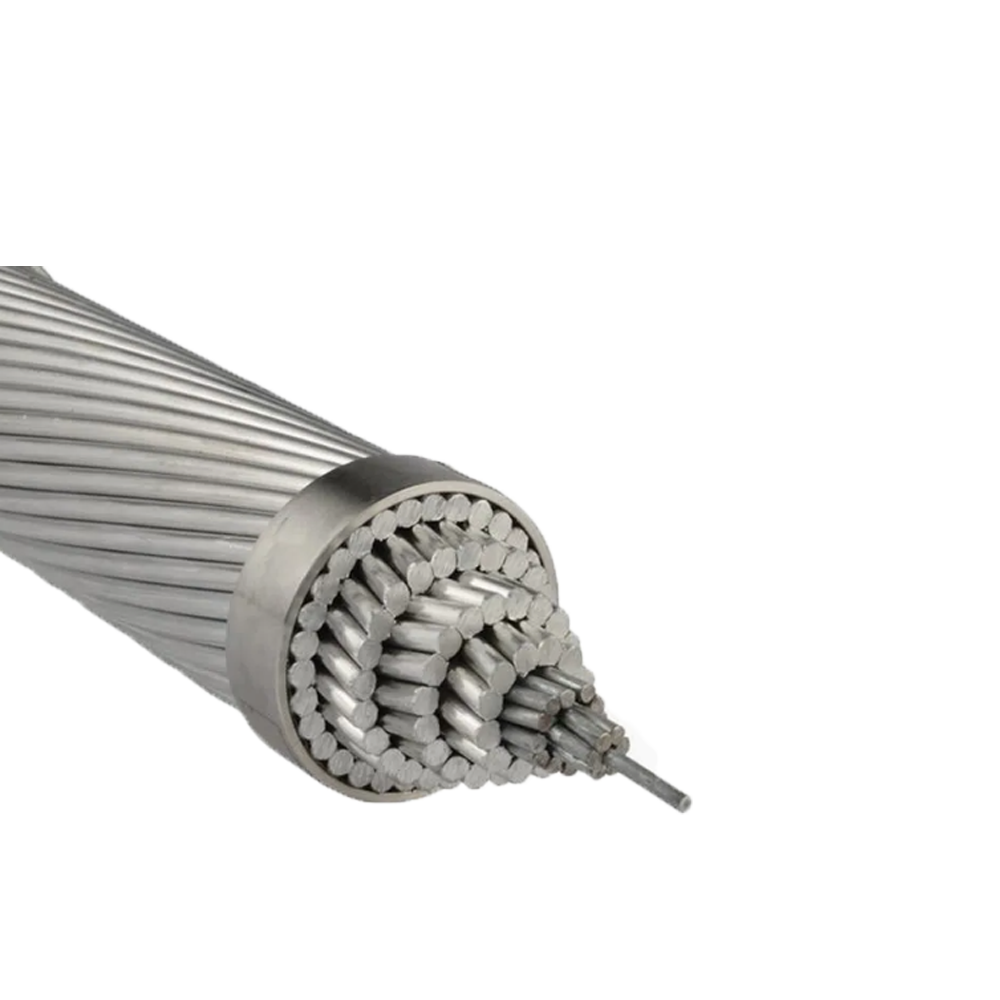
Proper installation practices are critical to achieving the full service life expected from aerial insulated cables. Incorrect tensioning, improper support spacing, or the use of incompatible hardware can introduce mechanical stress that accelerates insulation wear, even on a well-manufactured cable.
Medium-voltage cables with integrated messenger wires can typically support longer spans between poles, reducing the total number of support structures needed along a route. Low-voltage cables, being lighter, may require closer spacing depending on local wind and ice loading standards, and installers should always reference the manufacturer's sag-tension charts rather than relying on generic assumptions.
Using clamps, connectors, and grounding hardware specifically rated for insulated aerial systems prevents insulation damage during installation and ensures that fault currents are properly directed away from the line in the event of a failure. Mixing hardware designed for bare conductors with insulated cable systems is a common installation error that can compromise both safety and cable longevity.
While aerial insulated cables require less frequent maintenance than bare conductor systems, periodic inspection remains important to catch issues before they escalate into outages. Visual inspections should look for signs of jacket abrasion, sagging beyond design tolerances, or damage from wildlife such as woodpecker holes, which can compromise the insulation layer over time.
Utilities that implement a consistent inspection schedule typically see fewer unplanned outages and can extend the operational life of their aerial cable network well beyond the standard design expectations.
Choosing between medium-voltage and low-voltage aerial insulated cables, and selecting the appropriate specifications within each category, requires a clear understanding of the project's voltage requirements, span lengths, environmental exposure, and load growth expectations. Engineers should work closely with cable manufacturers to confirm that conductor sizing, insulation thickness, and jacket material align with both current needs and anticipated future demand.
A well-specified aerial insulated cable system reduces long-term maintenance costs, improves public and worker safety, and provides the reliability that modern power distribution networks increasingly require. As utilities continue to prioritize resilience against extreme weather and wildfire risk, insulated aerial cables are positioned to remain a central component of overhead distribution infrastructure for years to come.

We firmly believe that good cables are not only a competition of materials, but also a reflection of craftsmanship, quality, and responsibility.

Links
Product
Send Inquiry
No. 29 Sankeshu Road, Xuanzhou District, Xuancheng City, Anhui Province, China
+86-18621104555/+86-563-2622999
 Electrical Cable Manufacturer
OEM/ODM Wire and Cable Solutions
Electrical Cable Manufacturer
OEM/ODM Wire and Cable Solutions
 English
 Español
 عربى
عربى
 русский