

 English
 Español
 عربى
عربى
 русский
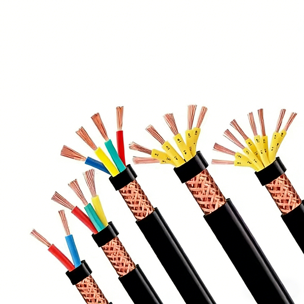
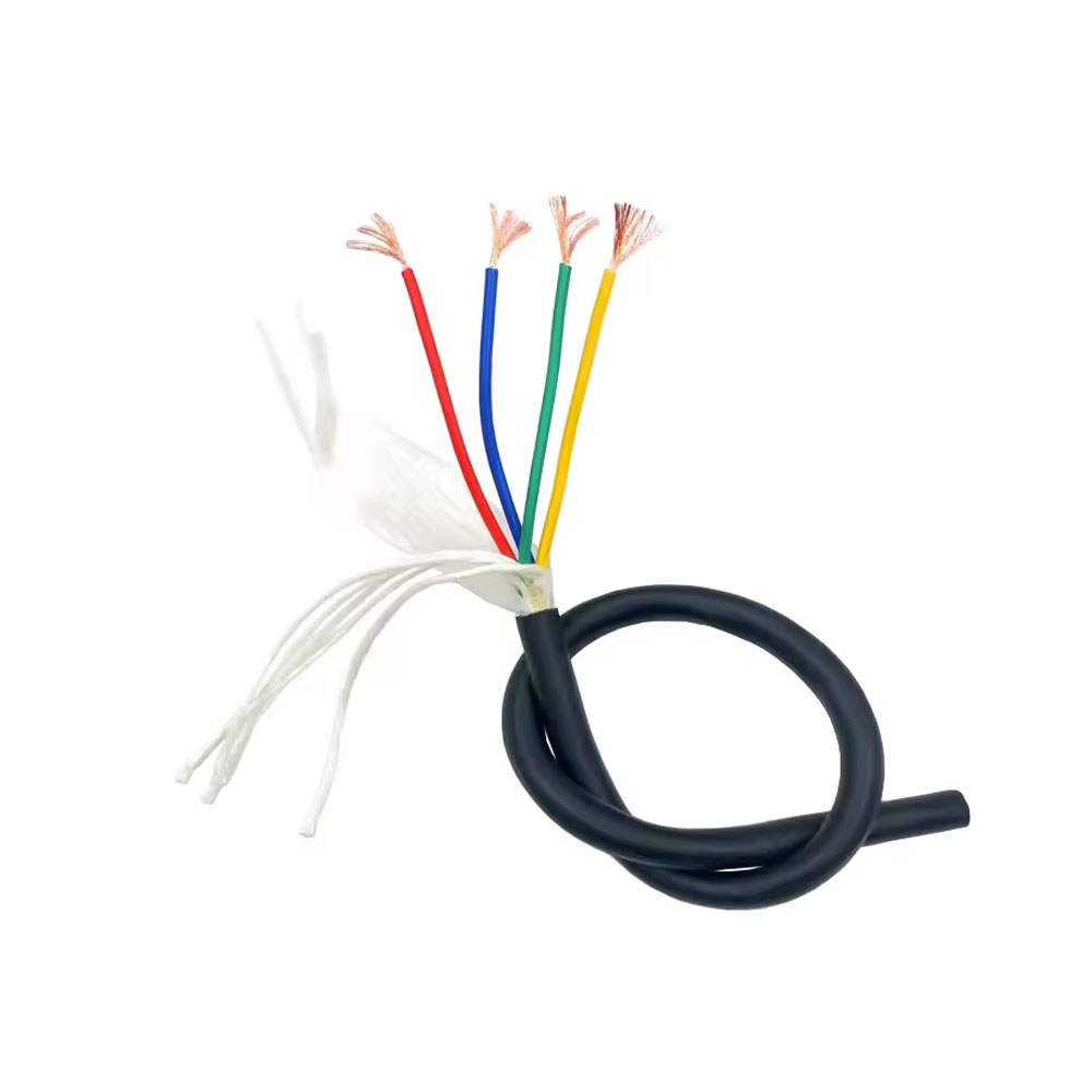
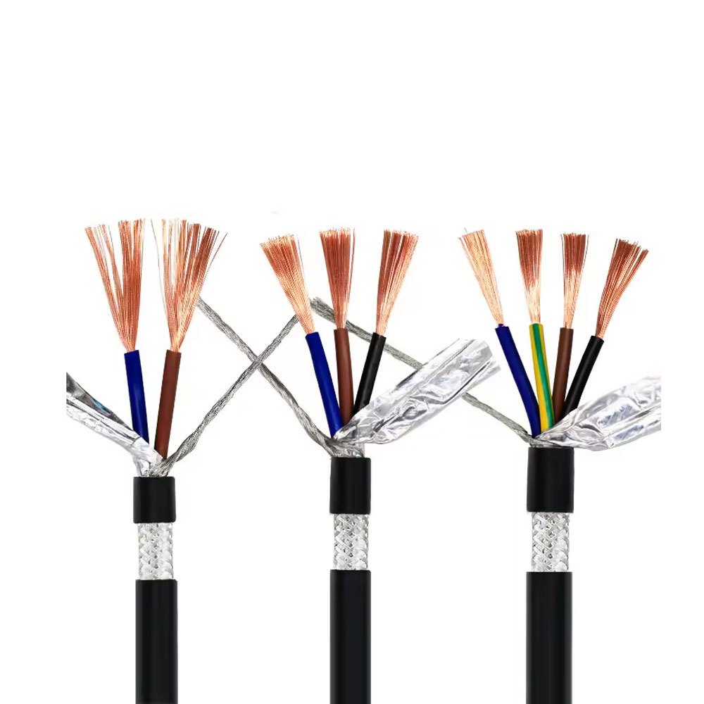
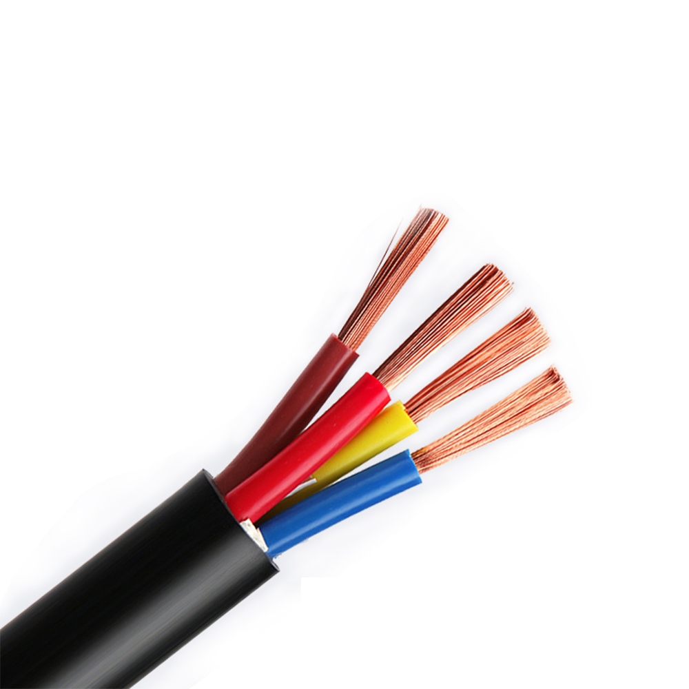
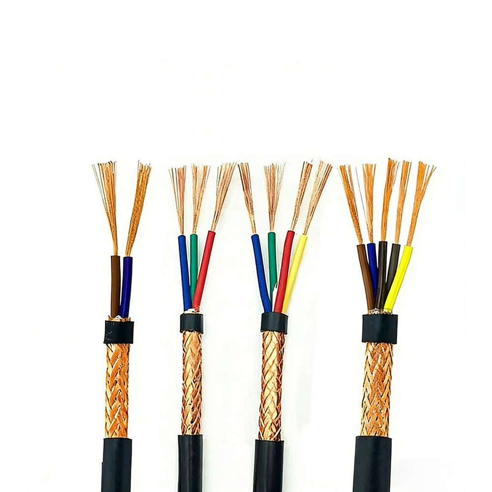
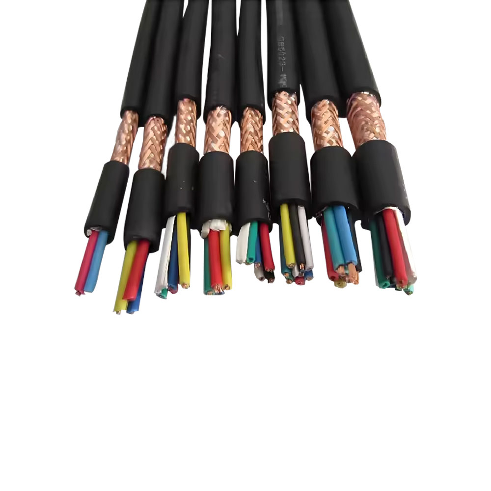
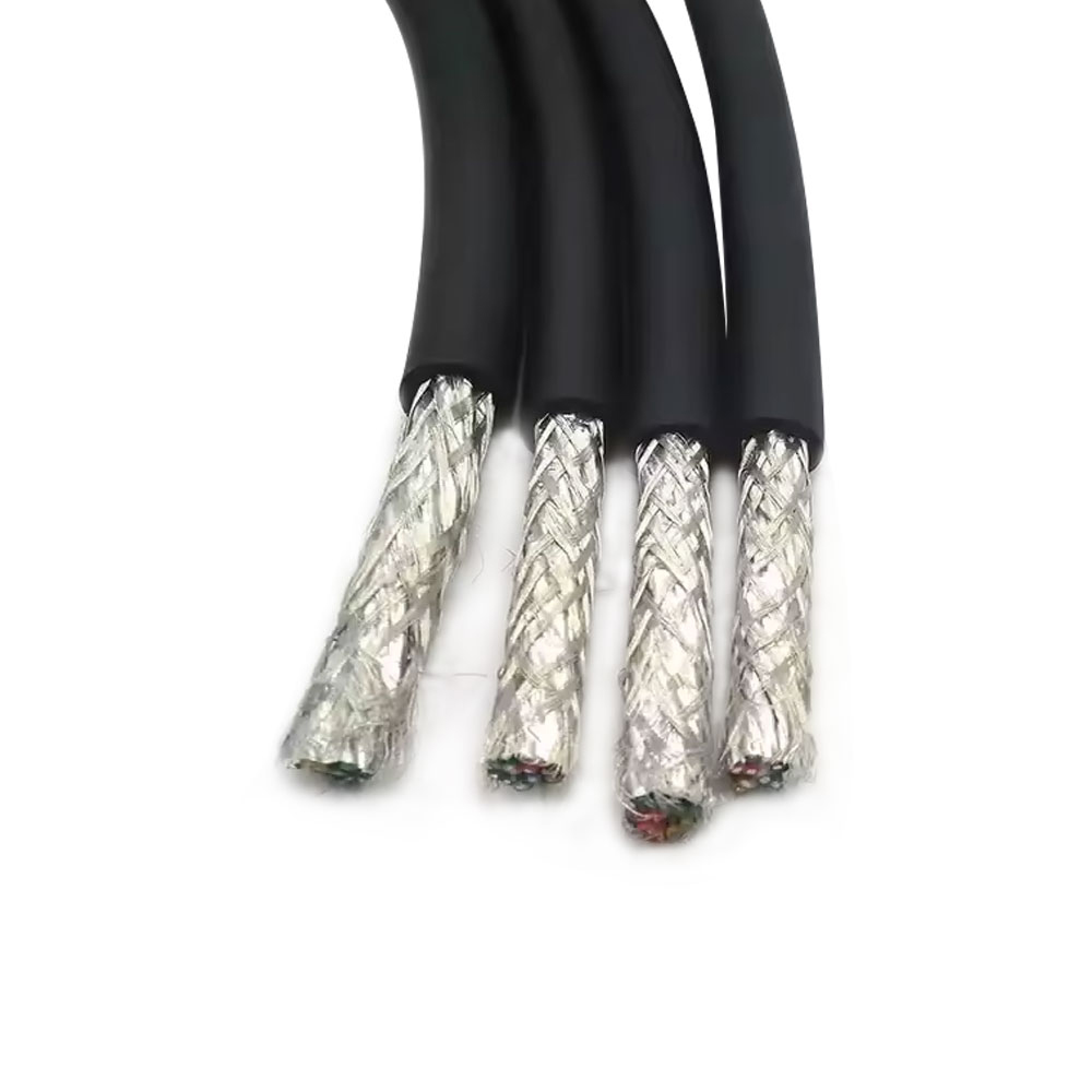


How Core Count and Stranding Configuration Affect Control Cable Routing in Multi-Axis Systems
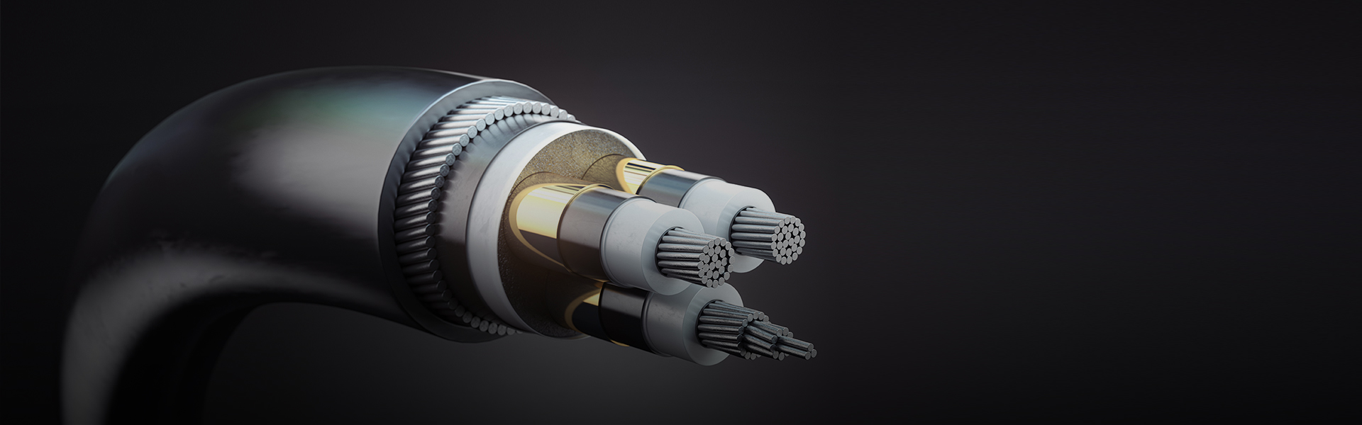
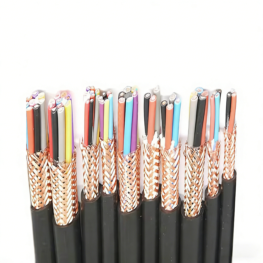
Multi-core control cables are specified by core count and conductor cross-section, but the internal stranding configuration — how individual cores are grouped, twisted, and laid within the cable — has a substantial effect on how the cable behaves during installation routing and how it performs over time in systems with multiple signal types sharing a common cable. In industrial automation and multi-axis motion control systems, control cables routinely carry a mix of digital I/O signals, analog sensor outputs, encoder feedback, and low-voltage power for solenoids or sensors — all within the same cable jacket. Managing the interaction between these signal types starts with the cable's internal architecture.
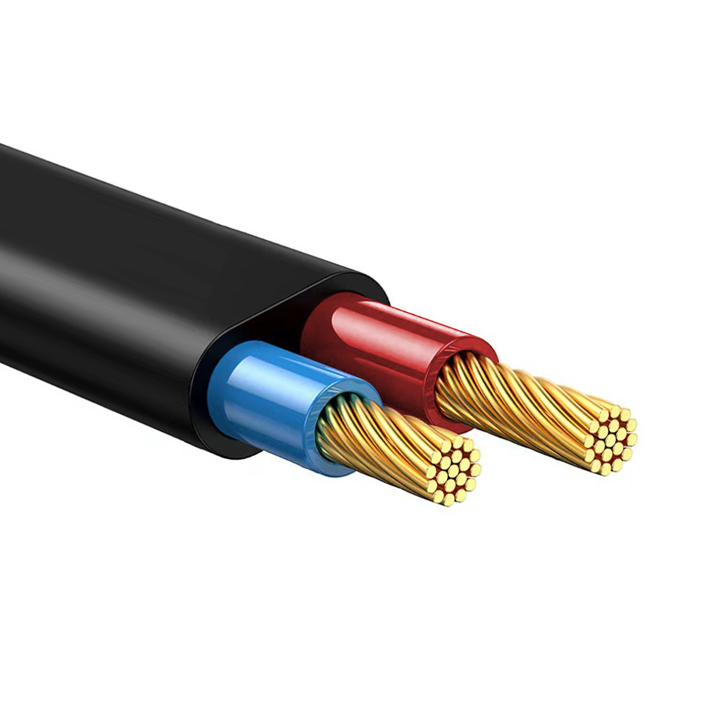
Cores in a multi-core control cable are typically arranged in one of three stranding patterns: concentric (cores laid in successive concentric layers), bunch stranding (all cores stranded together without specific layering), or sector/quadrant grouping (cores organized into functional sub-groups, often with individual shielding per group). Concentric stranding produces a predictable, stable outer diameter and ensures that no core is permanently positioned at the cable's outer edge — every core migrates between inner and outer positions as the cable is bent, distributing mechanical stress more evenly than bunch stranding, where specific cores may be consistently in high-stress positions. For control cables with 12 or more cores installed in continuously flexing applications, concentric stranding significantly extends service life compared to bunch-stranded equivalents of the same specification.
Quadrant grouping, where functionally related cores are stranded together into sub-units within the cable, allows different signal categories to be physically separated inside the cable. A common configuration places analog signal pairs in one quadrant, digital I/O cores in another, and power supply cores in a third, with the sub-units individually screened. This arrangement reduces capacitive coupling between power and signal cores — which would otherwise introduce switching noise onto analog signal lines — and allows each sub-unit to be identified and terminated separately at the control panel without spreading out all cores from a single bundle. The trade-off is increased cable diameter and cost compared to an unscreened, uniformly stranded design of the same core count.
Anti-Interference Design in Control Cables: Mechanisms Beyond Simple Shielding
Shielding is the most visible anti-interference feature of a control cable, but electromagnetic compatibility in industrial control applications requires a layered approach where shielding is one element among several design choices that collectively determine how well the cable rejects noise and avoids injecting interference into adjacent circuits. Specifying "shielded control cable" without understanding the full interference management architecture frequently results in installations that continue to suffer noise problems despite the presence of a shield.
The first mechanism is impedance matching between the cable and its termination. A control cable shield is only as effective as its termination impedance. A shield connected via a long pigtail wire to a chassis ground screw presents an inductive impedance that increases with frequency, making the shield connection increasingly ineffective at exactly the frequencies where radiated interference from variable frequency drives (VFDs) and switching power supplies is strongest — typically 150 kHz to 30 MHz. Low-impedance 360° shield termination using EMC cable glands or shield clamps that make circumferential contact with the shield over its full periphery maintains shield effectiveness up to the frequencies required for industrial EMC compliance. The pigtail length alone can raise the shield termination impedance by a factor of 10–100 at 10 MHz compared to a 360° termination, effectively negating the shield's benefit in the high-frequency range.
The second mechanism is capacitive separation between power and signal cores. Even within a shielded cable, power cores carrying switched currents from relay outputs or solenoid drivers capacitively couple interference into adjacent signal cores. The coupling is proportional to the mutual capacitance between cores, which depends on their separation distance and the dielectric constant of the insulation between them. Control cable designs that physically separate power cores from signal cores — using filler elements, internal partitions, or sub-unit grouping — reduce the mutual capacitance and consequently the noise injection without requiring additional shielding material.
The third mechanism is the use of individually twisted pairs for analog signals. Twisting an analog signal pair within the overall cable bundle provides differential noise rejection that is independent of the overall shield. A shielded but untwisted analog pair inside a multi-core control cable is exposed to inductive pickup from adjacent switched currents; the induced voltage appears as a common-mode signal on both conductors, but because the two conductors are at different positions within the bundle, they do not see identical induced voltages, and the difference appears as a differential (signal-corrupting) noise. Twisting the pair ensures both conductors alternate between inner and outer positions continuously, equalizing the induced voltages and allowing common-mode rejection at the receiver to cancel the noise effectively. For 4–20 mA analog control loops where the full-scale signal represents only 16 mA of current variation, even small differential noise currents produce significant measurement errors.
Voltage Ratings in Control Cables and Why the Rated Voltage Is Not the Maximum Permissible Signal Voltage
Control cables are typically rated at 300/500 V or 450/750 V (U0/U, where U0 is the voltage to earth and U is the voltage between conductors). These ratings are frequently misunderstood as the maximum signal voltage the cable can carry, but they actually define the insulation system's capability under test conditions and the system voltage classification that governs installation requirements — not the signal voltage in use.
The 300/500 V rating means the insulation is designed to withstand 300 V from any conductor to earth continuously, and 500 V between any two conductors. In industrial control systems operating at 24 V DC (the dominant control voltage in PLC and automation systems) or 110/230 V AC for high-voltage I/O, these ratings provide substantial margin above the actual operating voltage. The practical significance of the voltage rating is in two scenarios: impulse overvoltage and system fault conditions. Switching transients from relay contacts and solenoid coils can generate voltage spikes of several hundred volts superimposed on the normal control signal. The insulation must withstand these transients without partial discharge initiation, and the voltage rating is the parameter that ensures this margin exists. A 300/500 V rated cable operating at 24 V DC has approximately 12× margin against its rated conductor-to-earth voltage — sufficient for virtually all industrial transient environments when the cable is properly routed away from high-voltage equipment.
The second scenario is system fault conditions. In a multi-core control cable carrying both 230 V AC I/O signals and 24 V DC logic signals — a configuration found in retrofit automation projects where the control cable serves multiple functions — a fault that shorts a 230 V core to an adjacent 24 V core subjects the 24 V core's insulation to the full 230 V. If the cable is rated only for 300/500 V, this fault voltage remains within the insulation's design envelope. A cable rated at only 150/250 V in the same fault scenario may experience insulation breakdown that propagates the fault rather than containing it. Selecting control cable voltage rating based on the highest voltage present in the system — not the typical operating voltage — is the correct engineering approach.
Control Cable Color Coding Standards and the Challenges of Cross-Regional Projects
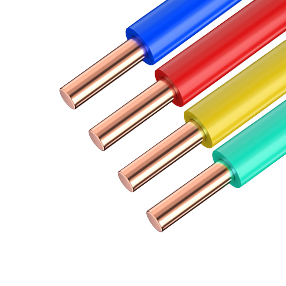
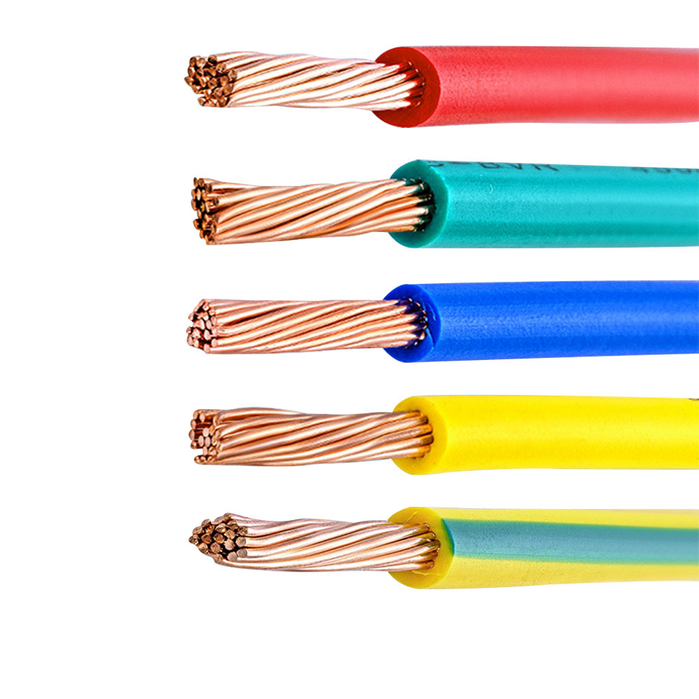
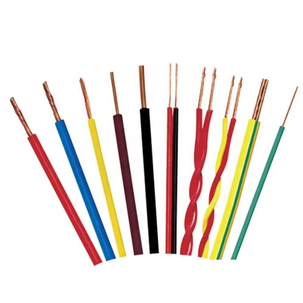
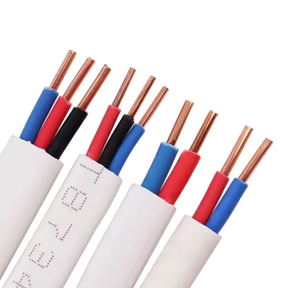
Core identification in multi-core control cables is governed by regional standards that differ significantly between markets. In projects involving equipment manufactured in one region and installed in another — or in OEM equipment exported to multiple markets — color coding conflicts require careful documentation and, in some cases, rewiring at the installation site. Understanding the dominant regional standards and their incompatibilities is essential for control cable procurement in international supply chains.
| Function | IEC 60446 / EU Standard | North America (NEC) | China (GB/T) |
| Protective Earth (PE) | Green/Yellow (mandatory) | Green or Green/Yellow | Yellow/Green (mandatory) |
| Neutral | Blue | White or Gray | Light Blue |
| L1 / Phase A | Brown | Black | Yellow |
| L2 / Phase B | Black | Red | Green |
| L3 / Phase C | Gray | Blue | Red |
The conflict most likely to create a safety incident is the treatment of blue and black cores. Under IEC 60446, blue designates neutral and black designates one of the live phases. Under North American NEC convention, blue designates a phase conductor and white/gray designates neutral. An electrician trained exclusively on one standard who encounters a cable wired to the other standard may incorrectly identify a live conductor as neutral. For this reason, international OEM equipment manufacturers often supplement color coding with numeric core identification — printed directly on the insulation jacket of each core — which provides an unambiguous identification system that is independent of regional color conventions. IEC 60228 and DIN VDE 0293 provide for numeric marking as an alternative or supplement to color identification, and control cable suppliers servicing export markets increasingly offer both color-coded and numbered-core options within the same cable construction.
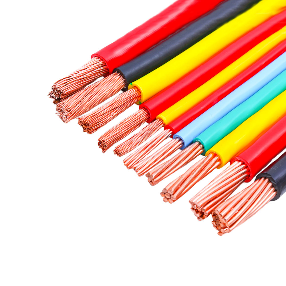
For high core-count control cables (19 cores and above), color-coding alone becomes impractical because the number of distinguishable colors with good visual contrast in typical industrial lighting is limited to approximately 10–12. Standard practice for high core counts uses a primary color plus numeric ring marking, or a systematic combination of base colors with tracer stripes (a colored stripe on a white or black base core jacket) that extends the distinguishable combination count well beyond the range achievable with solid colors alone.
Selecting Control Cable Cross-Section: Why Signal Current Is Rarely the Determining Factor
For most control and instrumentation cables, the signal currents are small enough that thermal ampacity is not the limiting factor in conductor cross-section selection. A 4–20 mA analog loop, a PLC digital input drawing 5–10 mA, or a proximity sensor consuming 50 mA at 24 V DC all generate negligible I²R heating in conductors as small as 0.14 mm². The actual constraints that drive conductor cross-section selection in control cables are voltage drop, mechanical robustness, termination compatibility, and fault loop impedance requirements — none of which relate to thermal ampacity.
Voltage drop is the dominant electrical constraint for 24 V DC control circuits. The permissible voltage drop depends on the device at the cable end: a PLC input module may specify a minimum input voltage of 15 V DC to guarantee logic-HIGH recognition, which means the cable must not drop more than 9 V from the 24 V supply under worst-case current draw. For a digital output driving a solenoid at 200 mA over a 50-meter cable run (100 meters of conductor length for the supply and return), the conductor resistance must be less than 9 V / 0.2 A = 45 Ω total. This requires a conductor resistance below 0.45 Ω/m, which corresponds to a cross-section of approximately 0.38 mm² in copper. Selecting 0.5 mm² provides margin; selecting 0.14 mm² (which has a resistance of approximately 0.13 Ω/m × 100 m = 13 Ω — within limits for very short runs but marginal at 50 meters) would produce unreliable operation at longer run lengths, even though the 200 mA current is thermally trivial for 0.14 mm² wire.
Mechanical robustness during termination is the practical lower limit for conductor cross-section in most industrial control applications. Conductors smaller than 0.25 mm² are prone to breaking at screw terminal connections if the conductor is not correctly seated before the screw is tightened, and are very sensitive to over-torquing. In control panels assembled by multiple technicians under production pressure, the consistency of termination quality for very fine conductors is significantly lower than for 0.5 mm² or 0.75 mm² conductors, which tolerate a wider range of termination technique. Most industrial control cable specifications settle on 0.5 mm² as the practical minimum for panel terminations, even when electrical requirements would permit smaller sizes.
Fault loop impedance requirements apply where control cables must carry overcurrent protection in compliance with IEC 60364-4-41 (protection against electric shock). In circuits where the fault loop impedance must be low enough to ensure operation of the overcurrent protective device within the required disconnection time, the conductor cross-section must be calculated from the fault loop impedance requirement rather than from normal operating current. This becomes relevant when control cables share a raceway or enclosure with 230 V AC circuits and the control cable conductors could become energized under fault conditions.
Control Cable Installation in Cable Trays: Segregation Rules and Their Engineering Rationale
Cable tray segregation for control cables is specified in IEC 61537, IEC TR 62490, and various national electrical codes, all of which establish minimum separation requirements between control and power cables. These requirements are frequently treated as bureaucratic formalities in practice, but each rule has a specific engineering rationale related to inductive and capacitive coupling, ground potential differences, and fault containment.
The primary coupling mechanism driving segregation requirements is inductive pickup from power cables carrying switched currents. Variable frequency drives produce current waveforms rich in high-frequency harmonic content — typical VFD output cables carry significant current components at 5th, 7th, 11th, and higher harmonics of the drive switching frequency (often 4–16 kHz carrier frequency), producing interference energy well into the hundreds of kilohertz range. Control signal cables routed in parallel and in close proximity to VFD output cables behave as the secondary winding of a loosely coupled transformer, with the induced voltage proportional to the rate of change of the magnetic field (dI/dt) and the area of the loop formed by the control cable conductors and their return path. The recommended minimum separation between VFD output cables and unshielded control cables in a common tray is typically 200–300 mm; for shielded control cables with properly grounded shields, 100 mm separation is often accepted, because the shield provides additional attenuation of the coupled interference.
Ground potential difference is a segregation concern specific to large industrial facilities where different sections of the grounding system may be at different potentials during transient events. A control cable running between two buildings or between remote sections of a large plant grounds its shield at both ends; if the ground potential difference between the two endpoints exceeds the common-mode rejection capability of the control system, the ground potential difference appears as a noise voltage on the signal. Routing control cables along the same path as power cables from the same distribution panel minimizes the ground potential difference between the cable shield terminations, because both the power and control systems reference the same ground point. This is the engineering reason behind the rule that control cables should follow the same physical route as the power supply to the controlled equipment rather than taking a direct shortest-path route across the facility.
Fault containment is the safety rationale for separating control cables from high-voltage power cables in cable trays. A fault in a high-voltage power cable — internal arc, insulation breakdown under short-circuit current — can produce enough energy to ignite the jacket of adjacent cables. Control cables that carry safety function signals (emergency stop, safety relay inputs, guard monitoring) must remain functional during a fire or fault event involving adjacent cables to allow the safety system to execute its shutdown sequence. IEC 62061 and ISO 13849 (functional safety standards) require that safety-relevant control cables be physically separated from non-safety cables or protected by fire-resistant barriers when installed in common cable trays. This is an increasingly common requirement in machine safety assessments, where the physical routing of safety control cables is part of the formal safety architecture documentation.
Control Cable Termination Practices That Directly Affect Long-Term Signal Integrity
The termination of control cables at terminal blocks, connector housings, and equipment panels is where the majority of field-induced signal integrity problems originate. Cable manufacturing quality provides the electrical performance potential; termination quality determines whether that potential is realized in the installed system. Several termination practices have a direct, measurable impact on the long-term reliability of control signals.
Ferrule Selection for Fine-Stranded Conductors
Control cables with Class 5 or Class 6 fine-stranded conductors require end-sleeve ferrules (DIN 46228 standard bootlace ferrules) at screw-cage terminal connections. The ferrule serves two functions: it consolidates the individual strands into a single geometric body that fills the terminal clamping zone correctly, and it protects the strands from being severed by the terminal screw during tightening. Ferrule size must match the conductor cross-section precisely — an oversized ferrule allows the compressed conductor to pull out under vibration; an undersized ferrule causes strand damage and high contact resistance. For conductors carrying 4–20 mA analog signals, contact resistance increases as small as 0.5 Ω at the terminal introduce a voltage error of 0.01 mV at 20 mA — negligible in itself, but cumulative across multiple terminations in a signal chain and progressively worse as oxidation increases contact resistance over time in humid or contaminated environments.
Shield Drain Wire Management
The drain wire of a foil-shielded control cable — the bare or tinned copper wire running in contact with the foil shield — must be handled carefully at cable ends to avoid degrading shield effectiveness. A common installation error is leaving the drain wire exposed beyond the shield termination point, forming an unshielded pigtail that can pick up interference and inject it directly into the terminal block. The drain wire should be terminated as close to the shield clamp or EMC gland as possible, with any excess cut back rather than coiled or bundled with signal conductors. At the equipment end of the cable (where the shield is grounded), the drain wire termination should be on a dedicated shield bar that connects to the cabinet PE terminal with the shortest possible conductor — not routed through the same terminal rail as the signal conductors, where induced currents in the drain wire could capacitively couple into adjacent terminals.
Bend Radius at Termination Points
The point where a control cable transitions from the cable tray into the terminal block is one of the highest mechanical stress locations in the installation. Bending a multi-core control cable sharply at this transition — to dress the cable neatly along the panel wall — creates permanent deformation of the cable core if the bend radius is tighter than the cable's minimum installation bend radius (typically 6–10× the outer diameter for fixed installation). Permanently deformed cores develop insulation micro-cracks at the bend point over time through repeated thermal cycling, and the cores at the outside of the bend carry higher conductor resistance due to work hardening of the copper strands at the deformed section. For control panels in environments with significant temperature cycling (outdoor cabinets, unheated industrial buildings), maintaining correct bend radius at termination points is as important for long-term reliability as any other installation parameter.