

 English
 Español
 عربى
عربى
 русский

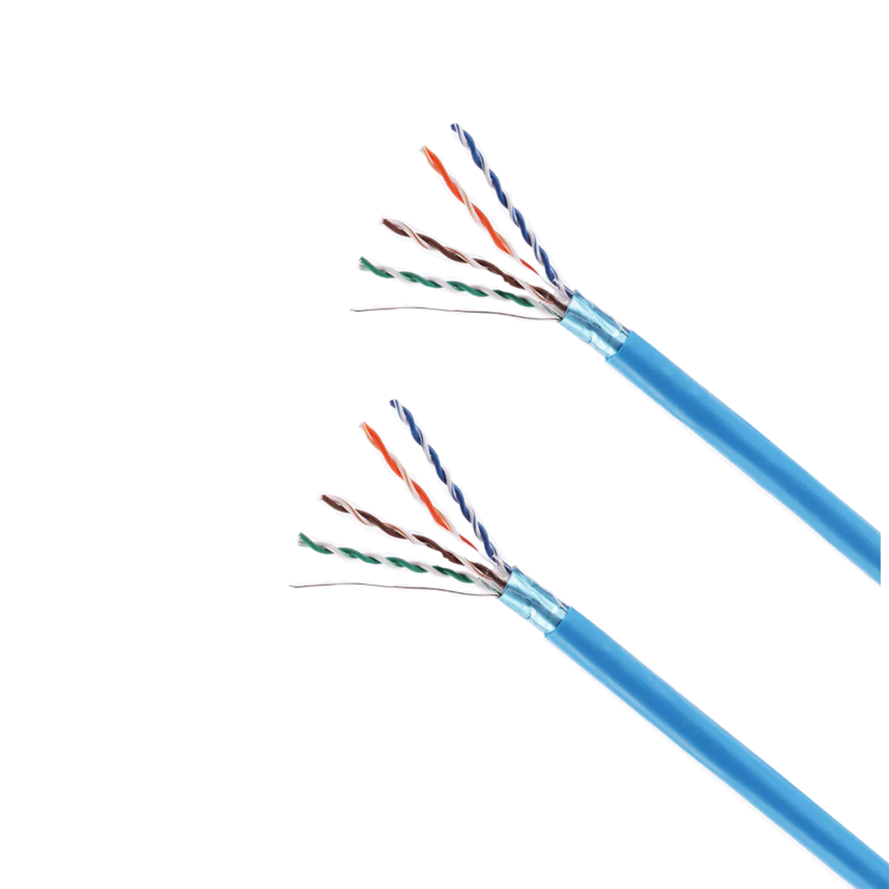
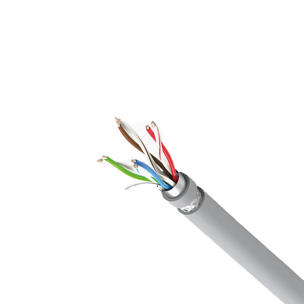



How Fieldbus Cable Electrical Parameters Are Defined by the Protocol and Why They Cannot Be Freely Substituted
Fieldbus cables are not generic signal cables with a fieldbus label — each major fieldbus protocol defines a precise electrical specification for its physical layer cable, and the cable's characteristic impedance, capacitance per unit length, and attenuation at the signal frequency are load-bearing parameters in the protocol's transmission model. Substituting a cable that does not meet these parameters changes the signal reflection behavior, the maximum network segment length, and in some protocols the permissible number of connected devices — often without any immediately obvious fault, but with degraded noise margins that manifest as intermittent communication errors under electrical disturbance conditions.
PROFIBUS DP, the most widely deployed fieldbus in process and factory automation, defines its physical layer cable in IEC 61158-2 and the PROFIBUS PA specification. The standard cable (Type A) is specified at 135–165 Ω characteristic impedance at frequencies above 100 kHz, a capacitance below 30 pF/m, a loop resistance below 110 Ω/km, and an attenuation below 3 dB/100 m at 100 kHz. These parameters are interdependent: a cable with correct impedance but excessive capacitance will correctly terminate reflections at node connections but will cause excessive signal degradation on long segments, reducing the effective maximum segment length below the 1,200 m specified in the standard. A cable with correct capacitance but low impedance will cause reflections at every passive stub connection that superimpose on the data signal, increasing the error rate particularly at the 12 Mbps maximum baud rate.
The reason characteristic impedance is so precisely specified for fieldbus cables relates to stub connections. In a PROFIBUS or DeviceNet segment, devices are connected via short stubs branching from the main bus cable. At each stub connection point, the bus cable sees a parallel impedance discontinuity. If the bus cable impedance is within specification, the discontinuity created by the stub is small and the reflected signal amplitude is below the noise threshold of the receivers. If the bus cable impedance is 20% below specification — which can occur when a low-cost unspecified cable is substituted — the reflected amplitude at each stub increases proportionally, and with the maximum 32 devices per PROFIBUS segment, the cumulative reflected energy can produce bit errors at 12 Mbps that do not appear at 1.5 Mbps, causing baud-rate-dependent communication reliability problems that are extremely difficult to diagnose without a bus analyzer and impedance measurement equipment.
Physical Layer Cable Specifications Across Major Fieldbus Protocols
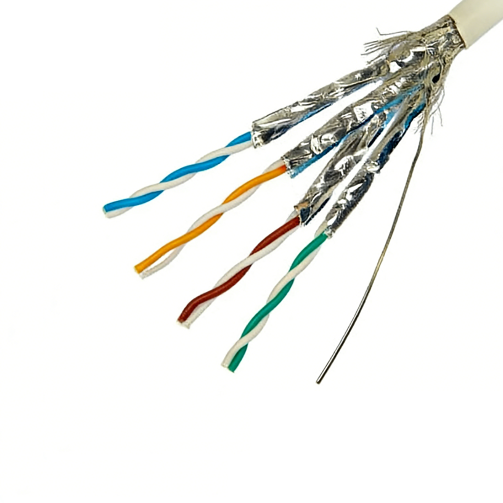
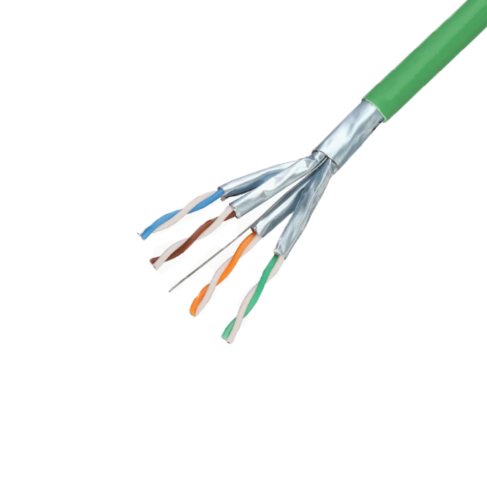
Each major fieldbus protocol has a distinct physical layer specification that defines the cable construction required for compliant installations. Using the wrong cable type — even one that appears visually similar — will result in a non-compliant installation that may pass initial commissioning at short segment lengths but fails at the maximum specified network extent or under worst-case noise conditions.
| Protocol | Impedance (Ω) | Max Capacitance (pF/m) | Max Segment Length | Cable Type |
| PROFIBUS DP (12 Mbps) | 135–165 | 30 | 100 m @ 12 Mbps; 1,200 m @ 9.6 kbps | Shielded twisted pair (Type A) |
| PROFIBUS PA | 100 | — | 1,900 m (Type A); 900 m (Type B) | Shielded twisted pair, IEC 61158-2 compliant |
| DeviceNet | 120 ± 10% | — | 500 m (thick); 100 m (thin) | Thick/Thin cable with power conductors integrated |
| CANopen | 108–132 | — | 40 m @ 1 Mbps; 5,000 m @ 10 kbps | Shielded twisted pair, ISO 11898-2 |
| Foundation Fieldbus H1 | 100 | — | 1,900 m (Type A) | Shielded twisted pair, IEC 61158-2 compliant |
| HART (4–20 mA overlay) | — | — | 3,000 m (typical loop resistance limit) | Shielded twisted pair; loop resistance critical |
| EtherCAT / PROFINET RT | 100 ± 15% | — | 100 m per segment | Industrial Ethernet Cat5e/Cat6 (IEC 61784-5) |
The segment length limits listed above are not cable length limits alone — they represent the maximum total electrical path length within which all signal reflections, propagation delay budgets, and attenuation limits can be satisfied simultaneously. For protocols with baud-rate-dependent segment lengths (PROFIBUS DP, CANopen), the limits at high baud rates are set by propagation delay — the round-trip signal propagation time from one end of the segment to the other must be less than the bit period of the protocol. At 12 Mbps PROFIBUS DP, one bit period is approximately 83 ns, and signal propagation in a cable with a velocity of propagation (VOP) of 66% of the speed of light covers approximately 8 meters per nanosecond — leaving very little margin for long segments. At lower baud rates, the bit period is long enough that propagation delay is no longer the limiting factor, and attenuation becomes the segment-length-limiting parameter instead.
The Role of Velocity of Propagation in Fieldbus Network Timing and How Cable Construction Affects It
Velocity of propagation (VOP) — the speed at which a signal travels through a cable expressed as a percentage of the speed of light in vacuum — is a fundamental parameter for high-speed fieldbus protocols where propagation delay determines maximum segment length. VOP is determined entirely by the insulation material's dielectric constant: VOP = 1/√εr × 100%, where εr is the relative dielectric constant of the insulation. A cable with a polyethylene insulation (εr ≈ 2.3) has a VOP of approximately 66%; a cable with PVC insulation (εr ≈ 3.5–4.5) has a VOP of approximately 47–53%. For a protocol with a propagation delay budget of 500 ns, the maximum cable length with PE insulation is 500 ns × 0.66 × 3×10⁸ m/s = approximately 99 meters; the same cable with PVC insulation allows only 71 meters — a 28% reduction in maximum segment length from insulation material choice alone.
This relationship explains why fieldbus cable specifications for high-speed protocols consistently require polyethylene or foamed PE insulation rather than PVC, and why substituting a PVC-insulated twisted pair cable that appears to meet the impedance specification will still produce a non-compliant installation at maximum segment lengths. The velocity of propagation also affects the cable's characteristic impedance: since Z₀ = √(L/C) where L is inductance per unit length and C is capacitance per unit length, and since higher εr increases C while leaving L approximately constant, a higher dielectric constant insulation produces a lower characteristic impedance as well as a lower VOP. A cable intended for 120 Ω (DeviceNet) specification with PE insulation cannot be replaced by a cable with the same physical dimensions but PVC insulation without the impedance falling below specification — further illustrating why insulation material and impedance are inseparable specifications for fieldbus cables.
For industrial fieldbus networks where different segments may use cables from different manufacturers (a common situation in retrofit installations), VOP inconsistency between cable segments creates timing anomalies. Two segments of nominally identical specification from different manufacturers with VOP values of 66% and 60% respectively introduce a 10% propagation delay difference that manifests as inter-segment timing jitter. In time-sensitive protocols such as EtherCAT and PROFINET IRT (isochronous real time), which synchronize distributed clocks across the network to microsecond accuracy, VOP variation between cable segments contributes a systematic timing offset that must be compensated by the network master during commissioning. Protocols that require sub-microsecond cycle time accuracy across 20 or more segments cannot tolerate high VOP variation without clock compensation mechanisms in the network master.
DeviceNet Cable: Why Power and Signal Integration in a Single Bus Cable Creates Unique Specification Challenges
DeviceNet is distinctive among major industrial fieldbus protocols in integrating both 24V DC device power and CAN-based data signaling within a single cable. The thick cable (standard trunk cable) contains five conductors: a CAN_H and CAN_L differential signal pair (typically 18 AWG), a power supply pair (typically 15 AWG for the thick cable), and a drain wire. This multi-function architecture simplifies installation by eliminating separate power cabling to field devices but creates specification challenges that do not exist for signal-only fieldbus cables.
The power conductors in a DeviceNet cable carry DC load current that can reach 8A on the trunk cable, generating I²R heat that elevates the temperature of the signal pair sharing the cable cross-section. At 8A through 15 AWG copper conductors, the DC resistance of 100 meters of trunk cable produces approximately 2.5 W of heat per conductor — enough to raise the cable interior temperature by several degrees above ambient in a cable tray installation with limited heat dissipation. This temperature rise affects the signal pair's characteristic impedance through thermal expansion of the insulation, increases the insulation's dielectric loss, and accelerates aging of the jacket compound. DeviceNet specifications limit the maximum current in the trunk cable not just based on the power conductor rating in isolation but based on the combined thermal effect on the signal pair performance — a consideration that disappears in signal-only cables where there are no power conductors generating heat.
Voltage drop on the power conductors is a second constraint that limits DeviceNet segment length independently of the signal transmission limit. DeviceNet devices require a supply voltage within a defined range (11–25V) at the device terminal; the 24V supply provided at the power tap must not drop below 11V at the most remote device. For a trunk current of 6A over 100 meters of thick trunk cable (15 AWG, loop resistance approximately 0.22 Ω/m), the voltage drop is 6A × 0.22 Ω/m × 100m × 2 (supply and return) = 26.4 V — far exceeding the available supply voltage. In practice, power taps placed at intervals along the trunk segment, combined with careful calculation of the maximum device current draw per segment section, are required to keep voltage at all device drops within specification. Fieldbus cable suppliers providing DeviceNet cable should provide not just the signal parameters (impedance, capacitance) but also the power conductor resistance per unit length and the temperature derating curves for both signal and power conductors at elevated ambient temperatures.
Shield Grounding in Fieldbus Cable Installations and Why Incorrect Grounding Causes More Problems Than No Shield
Fieldbus cable shields are among the most frequently misapplied components in industrial automation installations. The shield's purpose is to provide a low-impedance path for common-mode interference currents, preventing them from entering the signal pair as differential noise. Achieving this requires the shield to be grounded in a way that provides this path while preventing ground potential differences between grounding points from driving currents through the shield — currents that superimpose on the signal as common-mode noise and degrade communication reliability. The tension between these two requirements — ground the shield to divert noise, but avoid ground loops that inject noise — is resolved differently depending on the protocol and the specific noise environment.
For PROFIBUS DP, the standard recommendation is single-point grounding of the cable shield at the control panel end of each segment, with the field-end shield left floating or connected through a high-impedance earthing capacitor. This arrangement prevents 50 Hz ground loop currents from flowing through the shield — which is the dominant low-frequency noise source in most manufacturing plants — while still providing high-frequency EMI protection because the capacitive earth connection at the field end presents low impedance at frequencies above the ground loop frequency range. In practice, many installations ground the shield at both ends, which works correctly when all equipment in the segment shares the same ground potential. In large plants where the grounding grid potential between a control room and a distant field junction box may differ by 1–5V at 50 Hz, both-ends grounding drives significant 50 Hz currents through the shield, and the magnetic field from these currents induces differential noise in the signal pair — exactly the interference the shield was intended to prevent.
For PROFIBUS PA and Foundation Fieldbus H1, which are designed for operation in hazardous areas (Zone 1 and Zone 0) under ATEX and IECEx regulations, shield grounding must satisfy both EMC and intrinsic safety requirements simultaneously. In intrinsically safe installations, the shield must be grounded at one point only — the safe area — and the field-end shield must be isolated from ground by at least 1 MΩ to prevent the shield from providing a ground fault path that could exceed the energy limits of the intrinsically safe barrier. This grounding constraint is not negotiable under IS regulations; both-ends shield grounding on a PROFIBUS PA segment in a hazardous area invalidates the intrinsic safety certification of the installation regardless of whether the shield grounding creates a functional EMC problem.
Industrial Ethernet fieldbus protocols (EtherCAT, PROFINET) using Cat5e or Cat6 cables have their own shielding requirements. Standard structured cabling practice specifies 360° shield termination at both ends using EMC-rated RJ45 connectors or M12 circular connectors in industrial environments. Because Ethernet uses transformer-coupled interfaces that inherently reject common-mode interference at the receiver, the shield grounding philosophy for Industrial Ethernet is less critical than for RS-485-based fieldbuses — but the mechanical quality of the shield termination at the connector remains important, as high-impedance shield connections (pigtail drain wires) allow shield current return paths to develop at high frequency that degrade the cable's EMC performance above 100 MHz.
Fieldbus Cable Termination Resistors: Why They Are Required and How Incorrect Values Cause Network Instability
Bus termination resistors are a mandatory component of any RS-485-based fieldbus installation — including PROFIBUS DP, CANopen, and DeviceNet — yet they are among the most commonly incorrectly applied or omitted elements in fieldbus network troubleshooting cases. Their function is to absorb the energy of signals reaching the end of the bus cable and prevent signal reflections from propagating back toward the signal source. Understanding the physics of termination explains why incorrect resistor values — or multiple resistors applied at non-endpoint locations — are destructive to bus signal integrity.
When a signal propagates along a transmission line and reaches an impedance discontinuity, a reflected wave is generated with amplitude proportional to the reflection coefficient Γ = (Z_load − Z₀) / (Z_load + Z₀). At an open-circuit termination (Z_load → ∞), Γ = +1 and the reflected wave has the same polarity and full amplitude as the incident wave. At a short-circuit termination, Γ = −1 and the reflected wave has equal amplitude but opposite polarity. A termination resistor equal to the cable's characteristic impedance (Z_load = Z₀) produces Γ = 0 — no reflection. For PROFIBUS DP with Z₀ = 150 Ω, the termination resistor is specified as 150 Ω. For DeviceNet with Z₀ = 120 Ω, termination resistors are 120 Ω. For CANopen (also ISO 11898 physical layer), termination is 120 Ω at each end of the main bus.
The consequences of incorrect termination values are signal-level specific. A termination resistor 20% below specification (120 Ω instead of 150 Ω on PROFIBUS) creates a reflection coefficient of Γ = (120−150)/(120+150) = −0.11, producing a reflected wave at 11% of incident amplitude that superimposes on the signal at all nodes between the terminator and the signal source. For a PROFIBUS DP signal with 5V differential amplitude, the 11% reflection adds a 0.55V perturbation that arrives at each node one round-trip delay time after the original signal edge. At 12 Mbps, this delay is within the bit period for long segments, causing the reflected edge perturbation to occur during the sampling window of downstream receivers and increasing the bit error rate. Omitting termination entirely (open-circuit) produces full-amplitude reflections that can be large enough to violate the logic threshold of downstream receivers, causing complete communication failure at high baud rates even on short segments.
A frequently misunderstood rule is that termination resistors must be installed only at the two physical endpoints of the main bus cable — never at intermediate taps, spur connections, or T-junction points. Installing a termination resistor at an intermediate spur introduces a parallel impedance to ground at that point, reducing the effective bus impedance and generating a reflection at every signal transition, regardless of the resistor value. PROFIBUS repeaters, which regenerate the signal and establish a new bus segment, must be treated as a segment endpoint in terms of termination — each side of the repeater is a separate segment with its own pair of termination resistors at the segment endpoints.
Environmental and Mechanical Ratings for Fieldbus Cables in Harsh Industrial Installations
Standard fieldbus cables designed for panel wiring and light industrial environments are not suitable for installation in harsh process plant environments without explicit environmental rating verification. Oil refineries, chemical plants, food processing facilities, outdoor substations, and machinery with high vibration or continuous cable movement impose mechanical and chemical stresses that standard fieldbus cable jackets and insulation materials cannot withstand for the 15–25 year service life expected of process control infrastructure. Selecting fieldbus cables with appropriate environmental ratings for the installation condition is as important as selecting the correct electrical specification.
Chemical Resistance Requirements
Process plant environments expose fieldbus cables to hydrocarbons (oils, fuels, aromatic solvents), alkaline cleaning agents, acids, and steam — each of which degrades specific jacket materials at different rates. Standard PVC jackets have good resistance to aliphatic hydrocarbons (mineral oils, diesel) but swell significantly in aromatic solvents (toluene, xylene) and are attacked by concentrated acids and alkalis. Polyurethane (PUR) jackets provide excellent resistance to oils and fuels, outstanding abrasion resistance, and good low-temperature flexibility — making them the preferred jacket material for fieldbus cables in machine tool and mechanical engineering environments where cutting fluids, hydraulic oils, and coolants are present. However, PUR is susceptible to hydrolysis in high-humidity, high-temperature environments; a PUR-jacketed fieldbus cable installed in a steam-cleaned food processing area may degrade through hydrolytic chain scission of the urethane bond, causing the jacket to crack after 3–5 years. For steam-clean environments, cross-linked PE or polypropylene-based jacket compounds with demonstrated hydrolysis resistance are more appropriate despite their lower abrasion resistance compared to PUR.
Mechanical Durability in Moving Cable Applications
Fieldbus cables installed in robot arms, drag chains, or other continuously moving machinery must maintain their electrical parameters — particularly characteristic impedance and signal pair capacitance balance — throughout the cable's mechanical life. Impedance changes caused by conductor migration (cores shifting position within the jacket under repeated bending) alter the bus termination conditions and can cause a previously compliant network to develop reflections and communication errors after extended service. Fieldbus cables specified for continuous flexing applications use Class 6 fine-stranded conductors, thermoplastic elastomer (TPE) or PUR jackets, and stranding geometries with central fillers that prevent core migration. The minimum bend radius for continuous flexing applications is typically 7.5–10× the cable outer diameter, compared to 4× for fixed installation — exceeding the fixed-installation bend radius in a drag chain will cause the jacket to split and the cores to shift position within 1–3 million flex cycles, far short of the 10 million cycles expected for industrial drag chain applications.
Ingress Protection and Outdoor Installation
Fieldbus cables installed outdoors or in wet industrial environments must be rated for water immersion exposure beyond the IP67 or IP68 rating of the connected equipment. The cable's outer jacket must maintain its integrity when exposed to UV radiation, rain, temperature cycling from –40°C to +90°C, and ozone concentrations elevated above background in locations near electrical discharge equipment. UV-stabilized black polyethylene jackets with defined UV stabilizer content (typically HALS at 0.2–0.5% by weight combined with carbon black at 2–3%) provide adequate outdoor stability for 20-year service life. The critical installation point is that the cable's outdoor UV resistance is dependent on jacket integrity — any surface damage from abrasion, rodent attack, or installation stress that exposes the underlying insulation destroys the UV protection at that location and initiates rapid photodegradation. Outdoor fieldbus cables in installations with mechanical damage risk should include a protective outer layer of steel tape or corrugated steel armor beneath the jacket to prevent contact-induced jacket damage.