

 English
 Español
 عربى
عربى
 русский
UV Resistance and Thermal Aging: The Two Degradation Mechanisms That Determine Photovoltaic Cable Service Life
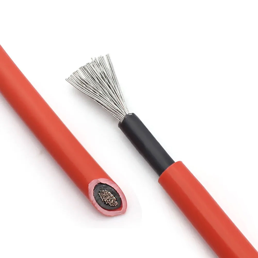
Photovoltaic cables are exposed to sunlight for their entire operational life — in rooftop systems this may mean direct irradiance accumulation exceeding 10,000 hours over a 25-year system design life, with surface temperatures on south-facing roofs regularly reaching 70–90°C during peak summer conditions. These two factors, ultraviolet radiation and sustained elevated temperature, are the primary degradation mechanisms that separate purpose-built PV cables from general-purpose outdoor cables, and understanding their interaction helps explain why cable material selection is not interchangeable between product categories.
UV radiation attacks polymer chains in the insulation and sheath through a photochemical process called photooxidation, which cleaves molecular bonds and progressively embrittles the material. Standard PVC, which is inherently UV-unstable without added stabilizers, can begin showing surface crazing and increased brittleness within three to five years of direct sun exposure. Cross-linked polyethylene (XLPE) and, more commonly in PV-specific applications, cross-linked EVA or XLPO (cross-linked polyolefin) compounds resist photooxidation far more effectively because their three-dimensional polymer network structure limits chain mobility and provides inherent resistance to molecular cleavage under UV exposure. The crosslinking process — whether achieved by peroxide chemistry or electron beam irradiation — also raises the material's continuous operating temperature rating from the 70°C limit of standard thermoplastic polyethylene to 90°C or 120°C for XLPE variants used in PV applications.
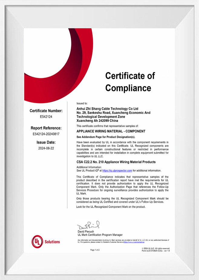
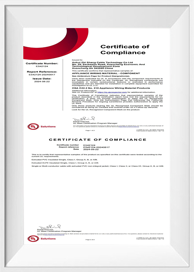
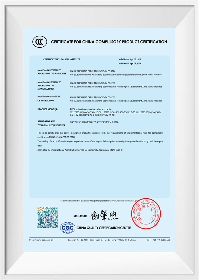
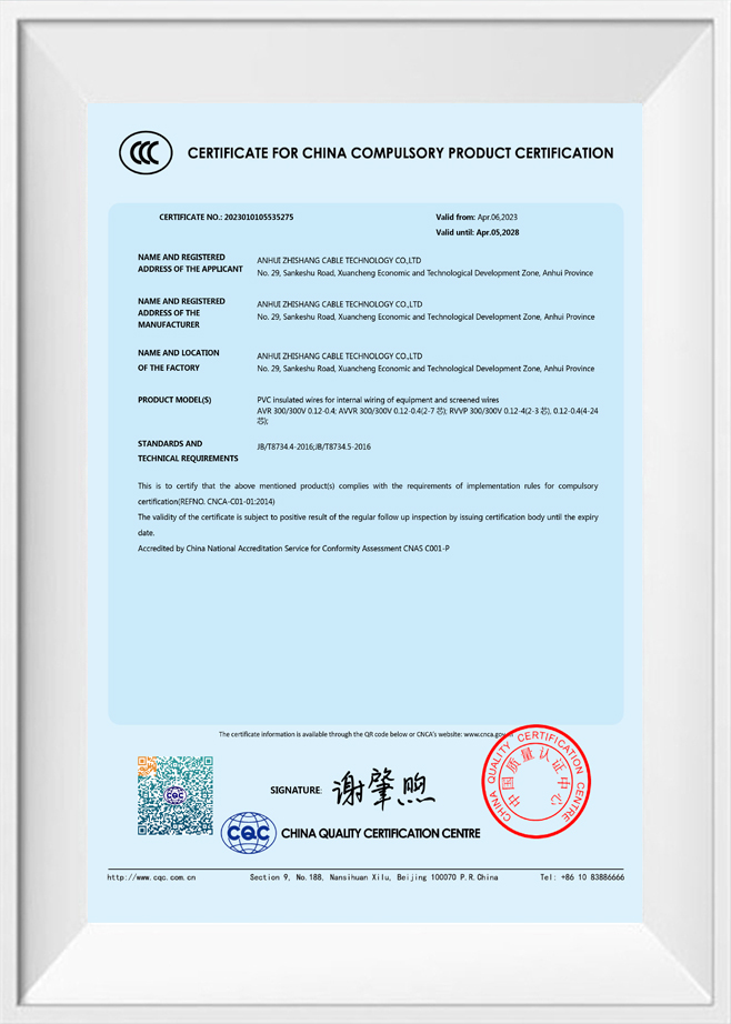
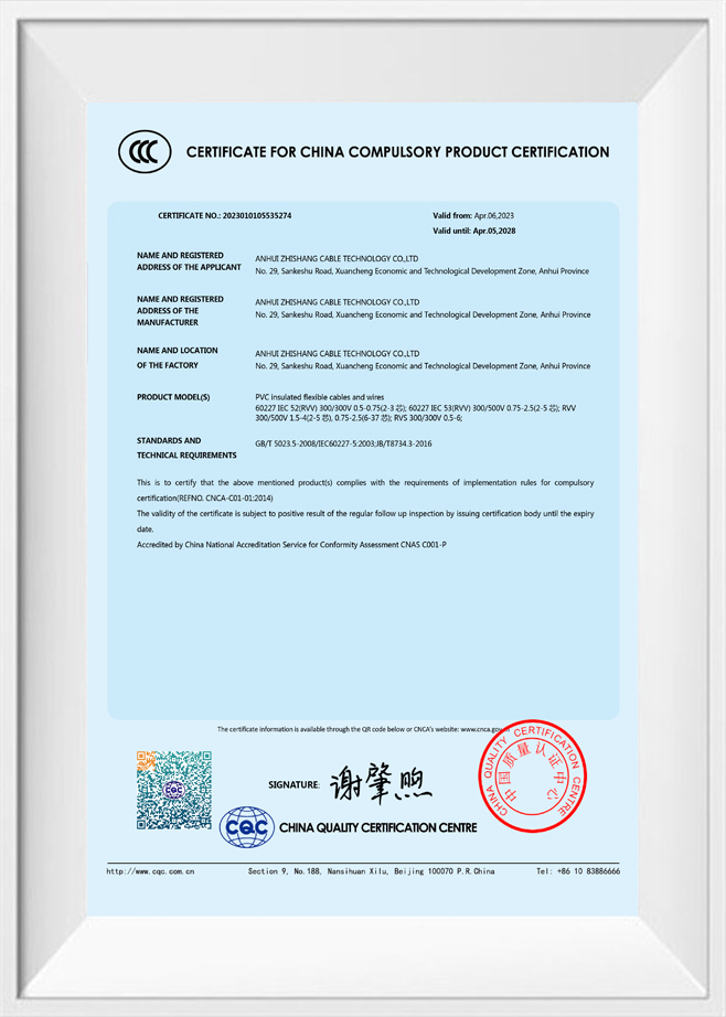
Thermal aging at sustained temperatures interacts with UV degradation in a non-linear way: elevated temperature accelerates the oxidation reactions initiated by UV, meaning a cable at 85°C degrades significantly faster than the sum of the individual temperature and UV effects would suggest. IEC 62930, the international standard for PV cables, addresses this by requiring an extended thermal aging test at 120°C for 3,000 hours in addition to UV exposure testing — a combined qualification that general-purpose cable standards do not include. Cables that carry CE marking under IEC 62930 have passed both tests with defined retention of elongation-at-break and tensile strength, providing objective evidence of compound durability that datasheets alone cannot supply. Anhui Zhishang Cable Technology Co., Ltd. qualifies photovoltaic cables to IEC 62930 requirements, ensuring that compound performance is validated through testing rather than inferred from raw material specifications.
DC Voltage Rating and the Difference Between System Voltage, Open-Circuit Voltage, and Cable Rating
One of the most consequential misunderstandings in PV system cable selection is the relationship between the system's nominal DC voltage, its maximum open-circuit voltage under cold conditions, and the voltage rating of the cable itself. These three values are distinct, and selecting a cable rated only to the nominal system voltage — without accounting for the open-circuit and temperature-corrected maximum — creates a latent insulation stress condition that may not produce an immediate failure but will accelerate dielectric aging and can lead to insulation breakdown years into the system's life.
In a crystalline silicon PV string, the open-circuit voltage (Voc) of each module increases as cell temperature decreases. A module with a nominal Voc of 48V at standard test conditions (25°C) may produce up to 56–58V at −10°C, depending on its temperature coefficient of voltage (typically −0.3% to −0.4% per °C for crystalline silicon). For a string of 20 such modules, this cold-temperature Voc reaches 1,100–1,160V — potentially above the 1,000V rating of a cable specified simply to "cover the 1,000V nominal system voltage." IEC 60364-7-712 and most national PV installation codes require cable voltage rating to cover the maximum string Voc under the lowest expected ambient temperature at the installation site, which for high-altitude or northern-climate installations may require 1,500V-rated cable even for systems designed around a 1,000V inverter input.
The shift from 1,000V to 1,500V system architectures in utility-scale and commercial rooftop PV has further sharpened this requirement. At 1,500V DC, the insulation stress on cable dielectric materials is not simply 50% higher than at 1,000V — dielectric breakdown probability is a strongly nonlinear function of field strength, and the gap between rated voltage and actual withstand voltage narrows significantly at higher operating potentials. Cables rated at 1,500V DC per IEC 62930 must pass a much more demanding voltage test (6,000V AC or equivalent DC) than 1,000V-rated cables, reflecting the real differences in insulation wall thickness and compound quality required at the higher voltage level.
| System Architecture | Nominal DC Voltage | Typical Cold-Temp Max Voc | Minimum Cable Rating Required |
|---|---|---|---|
| Residential rooftop | 600V DC | Up to 720V | 1,000V DC (IEC 62930) |
| Commercial / industrial rooftop | 1,000V DC | Up to 1,150–1,200V | 1,500V DC (IEC 62930) |
| Utility-scale ground mount | 1,500V DC | Up to 1,750V (cold climate) | 1,500V DC + site-specific derating |
Current-Carrying Capacity Derating in Bundled and Conduit-Routed PV String Cables
The ampacity values published in cable datasheets are based on a single cable in free air at a reference ambient temperature — conditions that rarely reflect actual PV installation practice. In reality, PV string cables are typically bundled together in groups, routed through conduit, installed beneath roof membranes with restricted airflow, or laid in direct contact with each other along cable trays on tracker structures. Each of these conditions reduces the cable's ability to dissipate heat, raising conductor temperature above the level assumed in the published ampacity rating. Ignoring derating factors leads to conductor temperatures that exceed the insulation's continuous rating, accelerating thermal aging and increasing resistance — which in turn raises operating temperature further in a self-reinforcing cycle.
Bundling derating is the most significant factor in typical PV installations. When multiple cables carrying current are in thermal contact or in close proximity, each cable's heat output raises the ambient temperature experienced by its neighbors. IEC 60364-5-52 provides grouping correction factors: two cables in contact retain approximately 80% of their individual ampacity, four cables grouped together retain around 65%, and six or more cables may retain only 57% or less depending on geometry. For a string cable rated at 25A in free air that is bundled with five other strings at the same current level, the derated ampacity per cable may fall to 14–15A — below the string's short-circuit current on a high-irradiance day. This situation requires either selecting a larger conductor cross-section or arranging cables in configurations that provide adequate thermal separation.
Ambient temperature derating adds a second correction layer. PV cables on rooftops in hot climates regularly experience ambient temperatures of 50–60°C in the space between roof surface and cable, compared to the 30°C reference temperature used in standard ampacity tables. For XLPE-insulated PV cable with a 90°C conductor temperature rating, the temperature rise allowance between ambient and conductor limit is only 30–40°C in these conditions, compared to 60°C in the reference case — reducing ampacity to approximately 70% of the tabulated value before any bundling correction is applied. Zhishang Cable provides application-specific ampacity guidance that accounts for both grouping and ambient temperature simultaneously, enabling system designers to select appropriate conductor cross-sections for actual installed conditions rather than relying on published free-air values that overstate the usable current capacity.
Connector Compatibility and the Hidden Risk of Mismatched PV Cable–Connector Combinations
MC4 and similar multicontact DC connectors have become the de facto standard termination for PV string cables, but the assumption that any MC4-compatible cable and any MC4 connector from different manufacturers can be freely combined is technically incorrect and, in some jurisdictions, a code violation. PV connector standards — including IEC 62852 and the system-level requirements of IEC 62548 — specify that connectors must be qualified for use with specific cable outer diameter ranges and conductor cross-sections, and that mixing connectors from different manufacturers voids the type-test qualification of both, even if the mechanical connection appears to seat correctly.
The risk in mismatched combinations is not primarily one of immediate failure — a mechanically seated mixed connector may function normally for months or years. The risk is contact resistance creep: thermal cycling during daily irradiance variation causes differential expansion and contraction between the cable insulation, cable conductor, and connector contact body, each of which has a different thermal expansion coefficient. In a matched and properly qualified combination, these differences are accounted for in the contact design. In a mismatched combination, the contact geometry may allow micro-movements that gradually increase contact resistance at the crimped interface, generating localized heat that eventually carbonizes the insulation and creates a resistive fault or arc. In DC systems without the zero-crossing that extinguishes AC arcs naturally, resistive faults can sustain arcing at surprisingly low fault currents — making connector quality and compatibility a genuine fire risk rather than a merely regulatory concern.
Cable outer diameter tolerance also matters more in PV connector applications than in most other connector types, because the connector's cable seal and strain relief depend on a close fit between the connector body and the cable jacket. A cable with an outer diameter at the lower end of its tolerance band may seat in the connector but leave the cable seal insufficiently compressed, allowing moisture ingress into the contact chamber — a direct path to insulation resistance degradation and connector corrosion in outdoor installations. Cables produced to tight outer diameter tolerances, with jacket wall thickness controlled to the upper end of the specification range, consistently produce better seal integrity across the full range of MC4-compatible connector sizes. This is a dimensional quality characteristic that is invisible at the point of purchase but becomes apparent over time in field reliability statistics, and is one of the construction details that Anhui Zhishang Cable Technology Co., Ltd. controls as a standard production parameter rather than an optional premium specification.
Key Checks Before Combining PV Cable and Connector from Different Suppliers
- Verify outer diameter compatibility: Confirm the cable's actual OD (not nominal) falls within the connector manufacturer's specified acceptance range for that connector size.
- Check cross-section crimp range: Each connector contact is qualified for a specific conductor cross-section range; verify the cable conductor fits within the crimp barrel's qualified range without modification.
- Confirm IEC 62852 compatibility statement: Some connector manufacturers publish tested compatible cable ranges; use this as the primary reference rather than assuming physical fit equals qualified compatibility.
- Use the correct crimp tool: Even matched cable-connector combinations fail if crimped with a tool not qualified for that connector; contact resistance and mechanical retention requirements in IEC 62852 are only met with approved tooling and die sets.