

 English
 Español
 عربى
عربى
 русский

Industry knowledge
How the Fiber Count and Optical Design Affect Transmission Performance
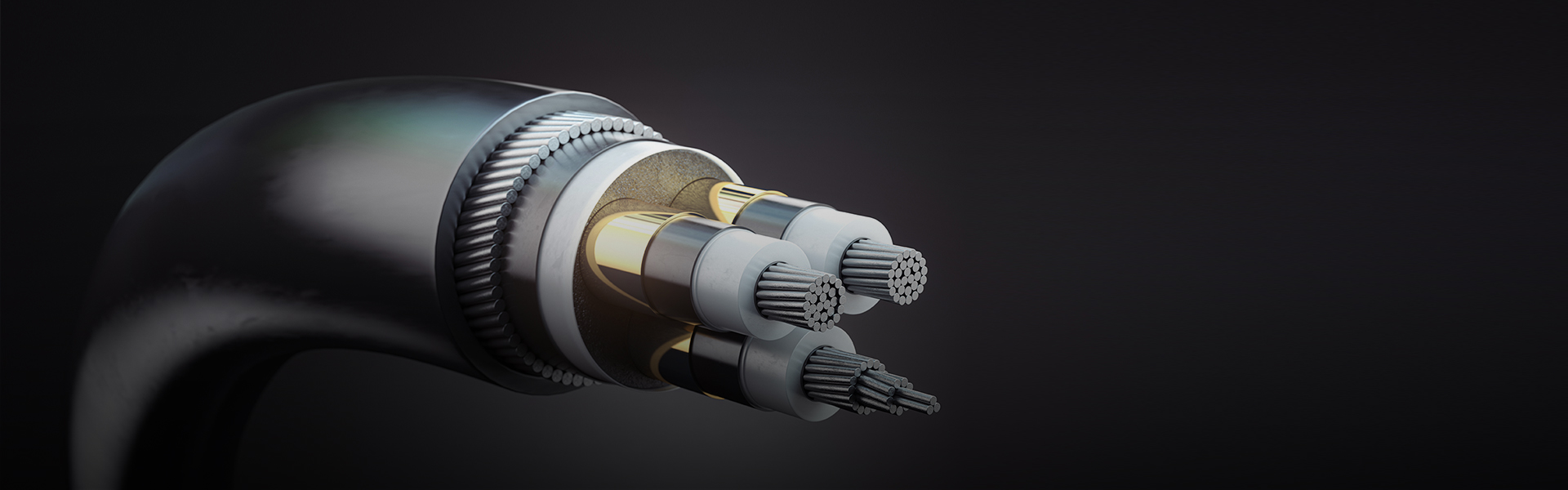
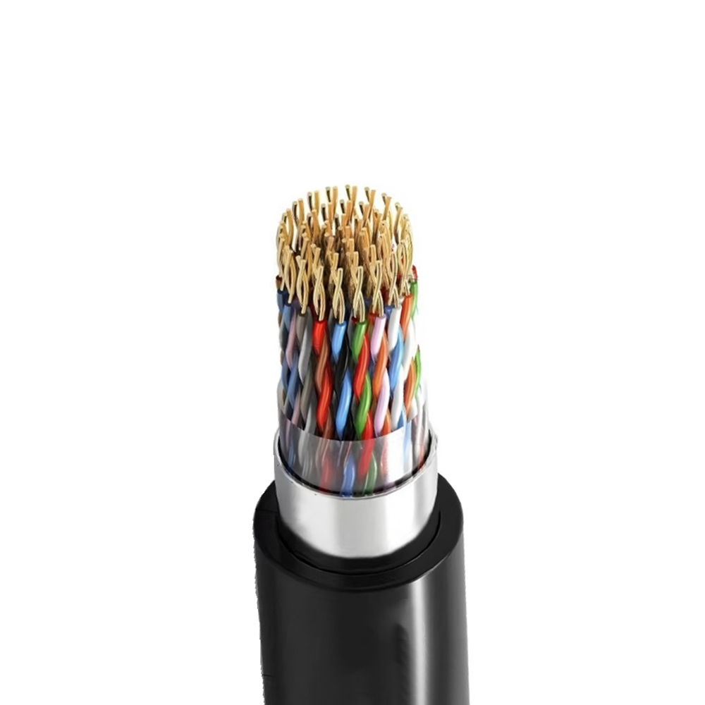
Fiber Optic Composite Cables are not one-size-fits-all products. The number of fiber cores — whether 2, 4, 12, 24, 48, or more — directly determines how much bandwidth capacity a single cable run can support, and the choice between single-mode (OS2) and multimode (OM3/OM4/OM5) fiber fundamentally changes the usable transmission distance. Single-mode fibers, with their 9/125 μm core/cladding ratio, are designed for long-haul transmission, commonly used in utility backbone runs or inter-substation connections where distances exceed several kilometers. Multimode fibers, with their larger 50/125 μm or 62.5/125 μm cores, are better suited for short-range, high-bandwidth data links within industrial plants or intelligent building systems.
A less-discussed but equally important factor is the stranding structure inside the cable. Loose-tube designs allow each fiber or fiber bundle to move slightly within a gel-filled tube, which protects against thermal expansion and contraction — critical in outdoor or industrial environments where temperature swings are significant. Tight-buffered designs encase each fiber directly in a protective coating, making them easier to terminate but more sensitive to mechanical stress. For composite cables that integrate both fiber and copper power conductors, understanding how these two components interact under bending, tension, and temperature loading is essential for long-term reliability.
Zhishang Cable engineers products with careful attention to fiber core arrangement relative to the cable's neutral axis, minimizing micro-bending losses that can silently degrade signal quality over time without any visible damage to the cable jacket.
Power Conductor Configurations in Composite Cable Design
The electrical portion of a fiber optic composite cable serves two distinct functions depending on the application: it can carry operational power for remote equipment such as cameras, sensors, or small communication nodes, or it can serve as a protective earthing and signaling medium within power utility infrastructure. These two use cases require very different conductor specifications, and selecting the wrong configuration leads to either over-engineered cables that waste cost or under-rated conductors that create safety hazards.
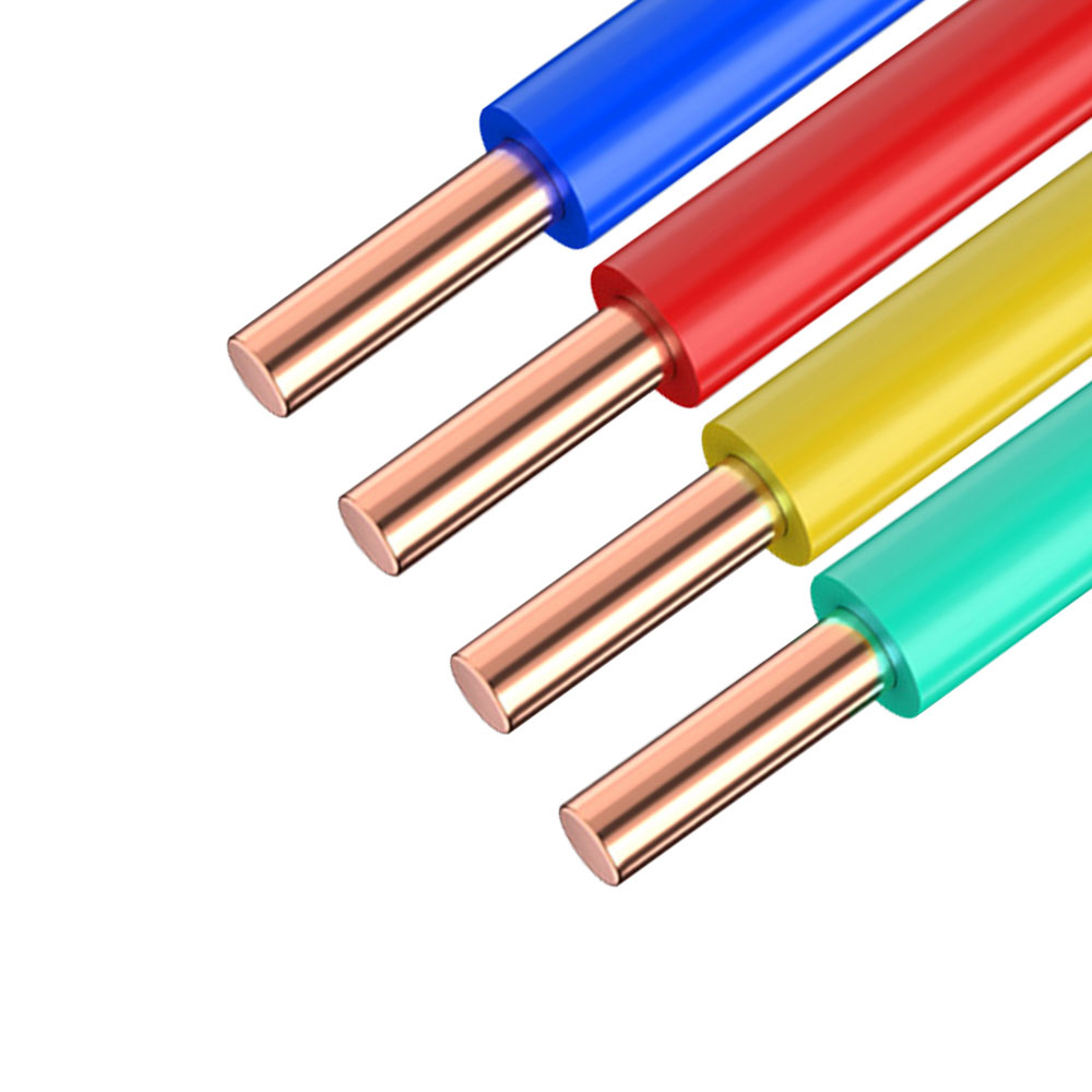
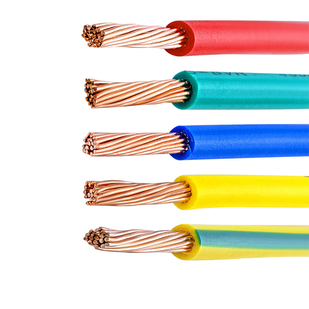
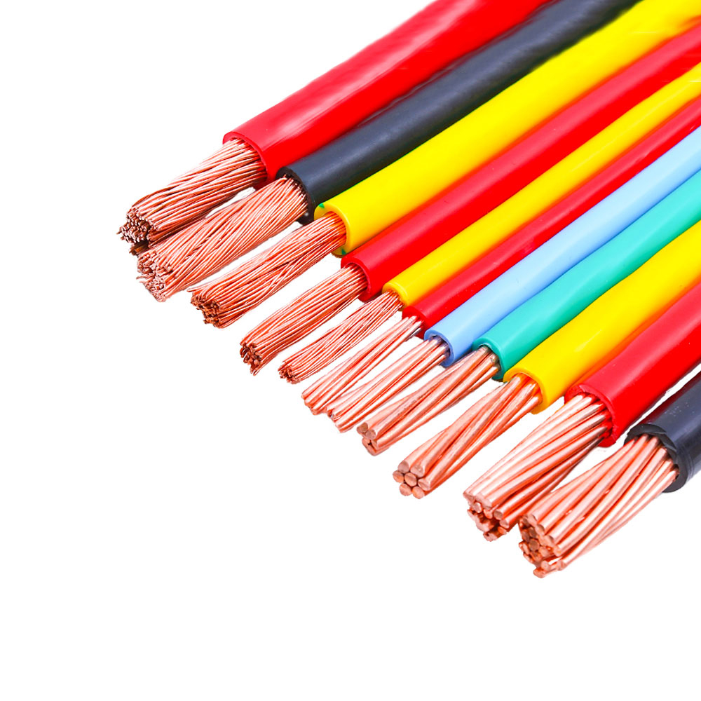
For low-voltage applications (typically 48V DC or 24V DC in industrial automation and surveillance systems), twisted-pair or parallel copper conductors with cross-sections between 0.5 mm² and 2.5 mm² are common. In utility-grade OPGW (Optical Ground Wire) or OPPC (Optical Phase Conductor) variants, the metallic elements are structural and electrical simultaneously, often using aluminum-clad steel (ACS) or aluminum alloy wires arranged in concentric layers. The DC resistance and short-circuit current capacity of these conductors must be calculated and verified against grid protection coordination requirements — a purely mechanical approach to cable selection is insufficient in these installations.
| Application Type | Typical Conductor Material | Cross-Section Range | Primary Function |
|---|---|---|---|
| Industrial Automation / Surveillance | Bare or tinned copper | 0.5 – 2.5 mm² | Low-voltage power supply |
| Utility Grid / OPGW | Aluminum-clad steel (ACS) | Varies by rated current | Ground wire + fault current path |
| Railway / Transit Systems | Copper or copper alloy | 1.5 – 6 mm² | Signaling power + data link |
| Smart Building / Weak Current | Tinned copper | 0.75 – 1.5 mm² | PoE / control signal |
Jacket Material Selection and Its Impact on Field Service Life
The outer jacket of a fiber optic composite cable is the first line of defense against environmental degradation, yet it is frequently treated as an afterthought in procurement. The dominant jacket materials — PE (polyethylene), PVC, LSZH (Low Smoke Zero Halogen), and TPU — each carry specific trade-offs that become critically important depending on the installation environment.
HDPE jackets remain the standard for direct-burial and outdoor aerial applications because of their outstanding moisture resistance, UV stability, and resistance to soil chemicals. However, HDPE does not perform well in fire scenarios — it burns without self-extinguishing. For cables routed through building risers, cable trays inside tunnels, or enclosed industrial facilities, LSZH jackets are required by most fire codes; they limit toxic gas emission and smoke density, which is especially important in confined spaces where evacuation may be difficult.
In dynamic applications — robotic arms, moving machine tools, or drag chain cable systems — neither PE nor PVC offers the repeated mechanical flex endurance needed. TPU (Thermoplastic Polyurethane) is the appropriate choice here, offering high abrasion resistance and flexibility retention even after millions of bend cycles. As part of its R&D-driven product development, Anhui Zhishang Cable Technology Co., Ltd. works with customers to specify jacket material based on actual service conditions rather than defaulting to the cheapest available option, recognizing that jacket failures are one of the leading causes of premature cable replacement in the field.
Key Jacket Material Properties at a Glance
- HDPE: Best moisture and UV resistance; suited for outdoor/direct-burial; not flame-retardant.
- PVC: Cost-effective with moderate flexibility; acceptable flame retardancy; releases HCl gas under combustion.
- LSZH: Low toxic emissions in fire; mandatory for tunnels, railways, and public buildings in many regions.
- TPU: Superior abrasion and flex-fatigue resistance; ideal for moving or drag-chain installations.
Installation Pitfalls That Degrade Composite Cable Performance Over Time
Even a well-manufactured fiber optic composite cable can underperform or fail prematurely if installation practices do not account for the cable's physical and mechanical characteristics. One of the most common mistakes is ignoring the minimum bend radius. For composite cables, this radius is not a single value but a dual constraint: the optical fibers and the copper conductors may have different minimum bend radius requirements, and the cable must be designed and installed to satisfy the more restrictive of the two. Violating the fiber's minimum bend radius introduces micro- and macro-bending losses; exceeding the conductor's limit can cause metal fatigue and increased resistance over time.
Pulling tension during conduit installation is another underappreciated risk factor. The maximum allowable tensile load (often specified separately for installation and long-term service) must not be exceeded. For cables with fibers supported by a central strength member (typically FRP or steel), the strength member carries most of the tensile force — but if the cable is gripped or pulled from the jacket rather than terminated correctly at the end, the load is transferred to the optical fibers or copper conductors instead. This is a particularly common error when installers unfamiliar with composite cable construction use standard pulling grips designed for all-electrical cables.
Thermal management during installation in hot environments or conduit runs exposed to direct sunlight is also frequently overlooked. Heat accelerates jacket degradation and can cause differential thermal expansion between the fiber elements and metal conductors. Specifying a cable with an appropriate operating temperature range — and verifying that conduit fill ratios allow adequate heat dissipation — extends service life considerably. Splicing and termination quality for the optical portion must also be verified using OTDR testing after installation, not just visual inspection, since connection losses that are within acceptable limits on day one can worsen significantly if the splice or connector was under mechanical stress from incorrect routing.