

 English
 Español
 عربى
عربى
 русский

Industry knowledge
Flame-Retardant Categories and What the Classifications Actually Mean in Practice
Flame-retardant control cables are not a single product category — they span a tiered classification system defined by IEC 60332 and its Chinese equivalent GB/T 18380, each tier reflecting a meaningfully different level of fire containment performance. The most commonly specified tiers are IEC 60332-1 (single cable vertical flame test), IEC 60332-3 (bundled cable vertical flame propagation test), and the more demanding IEC 60332-3-22 through 60332-3-25 categories, which differ in the total volume of cable material burned during the test. Understanding these distinctions matters because a cable that passes the single-cable test may still allow a fire to propagate when installed in dense cable trays alongside dozens of other cables — precisely the condition found in industrial control rooms, switchgear buildings, and process plant cable routes.
The IEC 60332-3 bundle test simulates real installation density by burning a 3.5-meter vertical ladder of cables with a defined total non-metallic volume per meter of tray. Category A (the most stringent) permits a non-metallic cable volume of up to 7 liters per meter of tray, while Category C allows up to 1.5 liters per meter — the lower the permitted volume, the easier it is to pass, because there is less combustible material to sustain the flame. Specifying a Category C cable for a densely populated cable tray where the actual installation density corresponds to Category A conditions is a common and dangerous miscalculation. Engineers selecting flame-retardant control cables for tray installations must calculate the actual non-metallic volume per meter of their intended cable fill and match it to the appropriate test category, not simply specify "flame-retardant" as a generic requirement.
Beyond flame propagation, LSZH (Low Smoke Zero Halogen) and LSHF (Low Smoke Halogen Free) variants introduce additional performance dimensions that are increasingly required in enclosed facilities. Standard PVC-insulated flame-retardant cables release hydrogen chloride gas and dense black smoke when they burn — HCl is corrosive to electronic equipment and toxic to personnel, and heavy smoke impedes evacuation. LSZH formulations eliminate halogen-based flame retardants in favor of mineral-based systems (typically aluminum trihydrate or magnesium hydroxide), which release water vapor rather than acid gases on combustion. Zhishang Cable produces both PVC-based and LSZH variants of flame-retardant control cables, with material selection matched to the specific environmental and regulatory requirements of each project.
How Flame-Retardant Additives Affect Electrical and Mechanical Cable Properties
Achieving flame retardancy in cable insulation and sheathing compounds is not chemically neutral — the additives that suppress combustion interact with the polymer matrix in ways that affect dielectric properties, flexibility, and long-term aging behavior. This trade-off is particularly significant in control cable applications, where insulation resistance, capacitance between conductors, and signal integrity over multi-core configurations are functional requirements that cannot be compromised in pursuit of fire performance alone.
In halogenated (PVC-based) flame-retardant compounds, antimony trioxide is commonly used as a flame-retardant synergist alongside the chlorine already present in PVC. While effective at suppressing ignition, high antimony trioxide loading increases insulation permittivity and reduces volume resistivity, which can raise capacitive coupling between adjacent conductors in multi-core control cables. For control circuits carrying low-level analog signals or high-speed serial communication, this elevated capacitance per unit length increases signal attenuation and limits the usable cable run length. Specifying insulation wall thickness and compound formulation with the actual signal frequency in mind — not just the flame class — is necessary to avoid this outcome.
LSZH compounds based on mineral filler systems present a different set of trade-offs. Aluminum trihydrate (ATH) must be loaded at very high concentrations (typically 50–65% by weight of the polymer compound) to achieve meaningful flame retardancy through its endothermic decomposition. At these loading levels, the compound becomes stiffer and more brittle than unfilled polymers, which reduces flexibility and cold-temperature performance. Manufacturers address this through elastomeric base polymers (EVA, EBA, or TPE) and surface-treated filler particles that improve dispersion and reduce the stiffness penalty. The result is a compound that can achieve both IEC 60332-3 flame performance and IEC 60811 cold-bend compliance — but only if the formulation is engineered specifically for this balance rather than assembled from commodity components. Anhui Zhishang Cable Technology Co., Ltd. validates compound performance through both flame and mechanical testing rather than relying on material supplier certifications alone, ensuring that the finished cable meets all specified parameters simultaneously.
| Compound Type | Flame Retardant Mechanism | Effect on Flexibility | Gas Emission on Combustion |
|---|---|---|---|
| FR-PVC | Halogen gas interrupts combustion chain | Moderate; plasticizer-dependent | HCl, dense black smoke |
| LSZH / ATH-filled | Endothermic decomposition, water vapor | Reduced; requires elastomeric base | Water vapor, low smoke, no HCl |
| LSZH / MDH-filled | Endothermic decomposition, higher temp range | Similar to ATH; better at high temperature | Water vapor, low smoke, no HCl |
| Phosphorus-based (intumescent) | Char layer forms, insulates surface | Good; lower filler loading needed | Low smoke, halogen-free |
Shielding Configurations in Flame-Retardant Control Cables and Their EMI Performance Implications
Control cables in industrial environments operate alongside variable-frequency drives, high-current switching equipment, and power cables — all of which generate electromagnetic interference that can corrupt low-level control signals if shielding is inadequate. In flame-retardant control cables, shielding must be designed not only for electrical performance but also for compatibility with the flame-retardant construction around it: the shield drain wire, binder tapes, and any metallic elements all interact with the overall cable's fire behavior and must not create thermal bridging or localized ignition points that undermine the cable's rated flame performance.
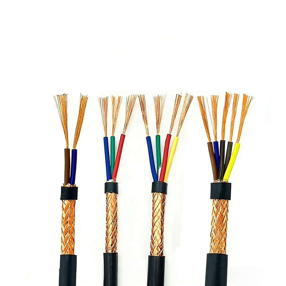
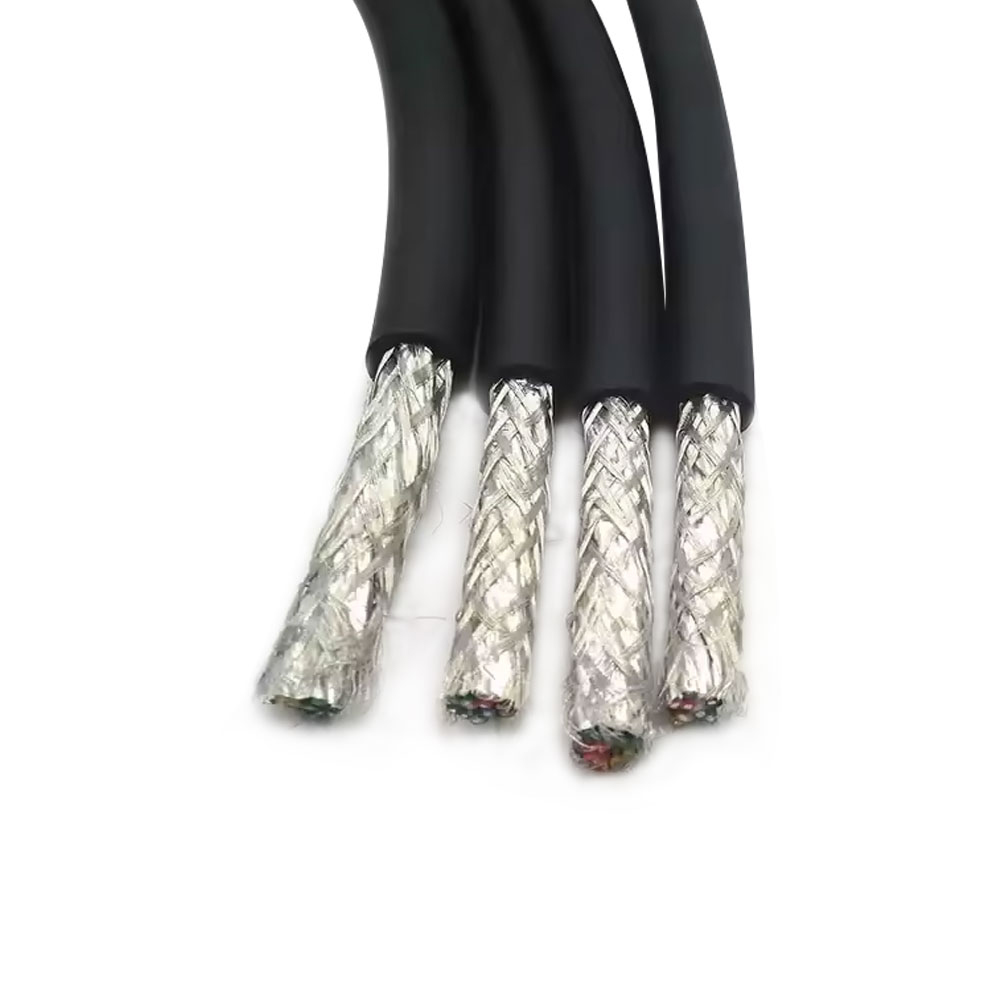
The two dominant shielding constructions in flame-retardant control cables are overall aluminum-polyester (Al/PET) foil shields with a drain wire, and overall or individual tinned copper braid shields. Foil shields provide near-100% optical coverage and are effective against capacitively coupled high-frequency interference, but their mechanical rigidity makes them vulnerable to tearing at the shield overlap joint during repeated flexing or installation pulling. Braided shields have lower optical coverage (typically 85–95%) but offer far superior mechanical robustness and lower shield resistance, which improves performance against inductively coupled low-frequency interference. For cables installed in fixed routes within switchgear rooms or DCS cabinets, foil-plus-drain construction is generally adequate; for cables routed through conduit or subject to movement during maintenance, braided shields are preferable.
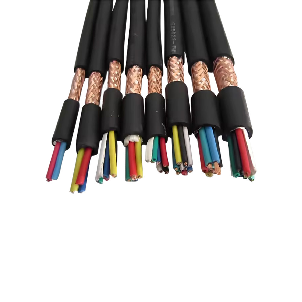
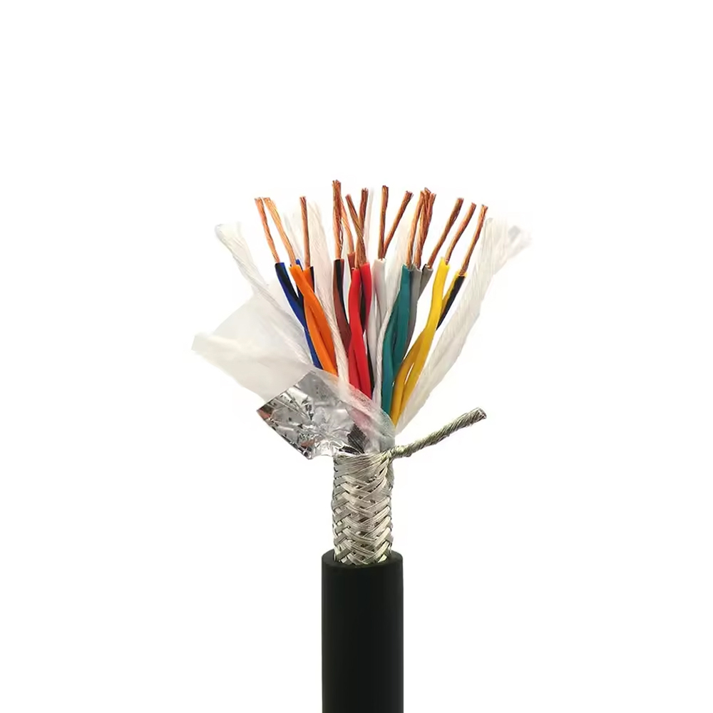
Multi-core control cables used for analog signal transmission (4–20 mA loops, thermocouple circuits, RTD connections) often require individual pair shielding in addition to an overall shield. Individual pair shields prevent inter-circuit crosstalk between signal pairs within the same cable — a significant concern when high-level signals (such as 24V digital I/O) and low-level analog signals (millivolt-range thermocouple outputs) share a common cable. The drain wire for each individual shield must be connected to earth at one end only to prevent shield current loops, which would reintroduce the low-frequency noise the shield was intended to block. This grounding discipline is as important as the shield material itself and must be specified clearly in cable installation and termination documentation.
Common Shielding Configurations and Typical Applications
- Overall Al/PET foil + drain wire: Cost-effective high-frequency EMI protection; suited for fixed DCS/PLC signal cable runs; vulnerable to foil damage if flexed repeatedly.
- Overall tinned copper braid: Better mechanical durability and low-frequency shielding effectiveness; preferred for conduit installations or environments with significant 50/60 Hz interference sources.
- Individual pair foil + overall braid (double shield): Highest inter-circuit isolation; required when mixed signal levels share a cable; used in precision analog instrumentation loops.
- Unshielded (screened by armoring only): Suitable for digital control signals with inherent noise immunity (e.g., 24V DC switching); not appropriate for analog measurement circuits.
Core Count and Grouping Strategies for Multi-Circuit Control Cable Installations
The decision of whether to run many small-core-count cables or fewer large-core-count cables for a multi-circuit control installation has consequences for fire risk, maintenance access, and long-term flexibility that extend well beyond the initial cable procurement cost. Dense bundles of individually jacketed small cables in a tray increase the total non-metallic volume per meter, raising the effective combustion load even when each individual cable carries a flame-retardant rating. Consolidating circuits into fewer multi-core cables reduces tray fill and combustion load, but creates a single point of failure where damage to one cable can affect multiple unrelated circuits simultaneously.
A practical approach used in process industries and power generation facilities is to group circuits by functional system rather than by geographic proximity, with separate cables for safety-critical circuits (emergency shutdown, fire and gas detection) and operational control circuits (process control loops, motor starters, instrumentation). This segregation ensures that a single cable failure cannot simultaneously disable both the process control function and its safety backup. It also simplifies fault finding and cable replacement, since a failure in one functional group does not require disturbing the wiring of another. Many installation standards — including IEC 60364 and facility-specific engineering standards in the petrochemical and power sectors — mandate this kind of circuit segregation explicitly.
Spare core planning within multi-core control cables is another aspect that is frequently undervalued at the specification stage. Installing cables with 10–20% spare cores at the time of initial construction costs very little relative to total project value, but adding circuits after construction requires new cable pulls that are disruptive, expensive, and sometimes physically impossible through congested existing routes. Spare cores should be distributed across cable groups rather than concentrated in a single cable, and their locations documented systematically so they can be identified and activated without extensive tracing work. As part of its application support capability, Zhishang Cable works with engineering teams to optimize core count selection based on projected system expansion scenarios, helping avoid the common situation where cable infrastructure becomes the limiting constraint on plant modifications within just a few years of commissioning.