

 English
 Español
 عربى
عربى
 русский
Industry knowledge
Why Aerial Insulated Cables Replace Bare Overhead Conductors and What the Transition Requires
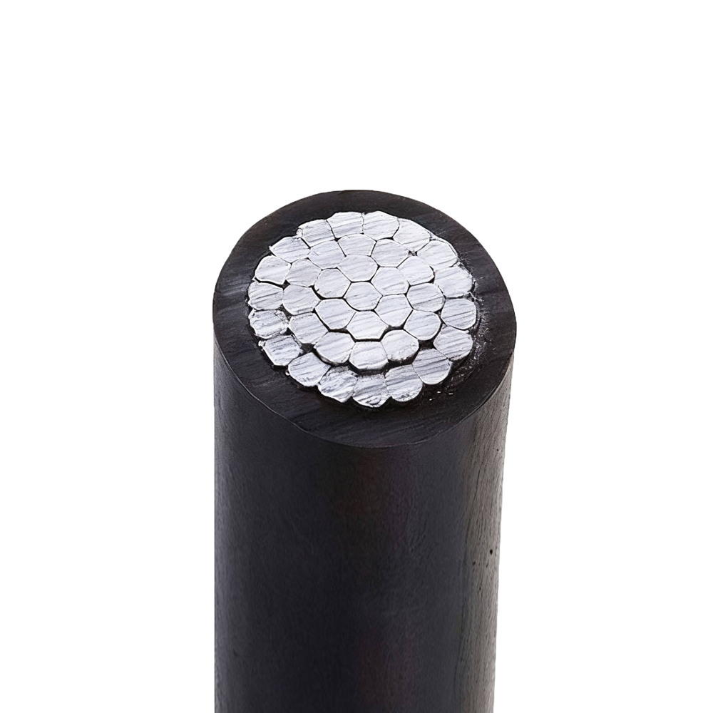
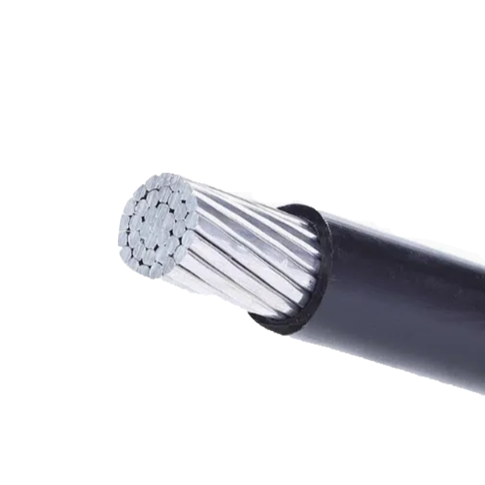
The replacement of bare overhead conductors with aerial insulated cables (AIC) in distribution networks is driven by a combination of safety, reliability, and maintenance factors that compound significantly in specific installation environments. Bare conductors on wooden or concrete poles have been the standard overhead distribution technology for over a century, but their performance in densely vegetated areas, coastal environments, and high-fault-rate urban networks has driven widespread adoption of insulated alternatives beginning in the 1970s in Scandinavia and progressively adopted across Asia, Africa, and Latin America over the following decades.
The primary technical advantage of aerial insulated cables over bare conductors is fault current reduction from conductor-to-conductor and conductor-to-tree contact. A bare 11 kV distribution line passing through tree canopy requires a clearance corridor of 2–3 meters on each side to prevent branch contact under wind loading; an insulated aerial cable can tolerate direct branch contact without fault initiation because the insulation withstands the contact voltage for the duration of the contact event. This allows right-of-way widths to be reduced by 40–60%, significantly reducing land clearing costs and environmental impact in forested regions. The insulation does not provide permanent contact tolerance — sustained branch pressure will eventually abrade the jacket and penetrate to the conductor — but it converts potentially fatal instantaneous faults into manageable slow-developing conditions that can be detected and cleared before becoming outages.
The transition from bare to insulated aerial systems requires changes in hardware, installation practice, and protection system coordination that are often underestimated in project planning. Bare conductor pole fittings — clamp-top insulators, spool insulators, and crossarm hardware — are not compatible with AIC installation, which requires messenger wire support systems, preformed helical grips, suspension clamps, and strain clamps designed for the specific cable outer diameter and mechanical tension rating. Protection relay settings calibrated for bare conductor fault currents must be recalibrated for insulated cables, where the insulation delays fault development, changing the time-current profile seen by overcurrent relays. Utilities that install AIC conductors on hardware designed for bare conductors, or that fail to adjust protection relay settings, frequently experience either missed fault detection or nuisance tripping in the transition period.
Messenger Wire Design in Low-Voltage Aerial Bundled Cables and Its Effect on Sag and Tension
Low-voltage aerial bundled cables (ABC, typically 0.6/1 kV rated) are available in two mechanical configurations: with a dedicated bare or insulated messenger wire that carries the full mechanical load of the bundle, and self-supporting configurations where one of the insulated conductors serves as the mechanical neutral. The choice between these configurations has significant consequences for span length capability, installation tension, sag behavior under temperature variation, and long-term mechanical reliability.
In messenger-supported ABC, the messenger wire is typically a galvanized steel wire or a steel-reinforced aluminum conductor (ACSR) selected independently of the electrical current requirements. The messenger carries the catenary load of the entire cable bundle, and the insulated conductors hang from it using cable ties or preformed grips at regular intervals — typically every 0.5–1.0 meters along the span. The mechanical design of the messenger is governed by the cable's maximum design span, the wind and ice loading conditions applicable to the installation region, and the maximum permissible sag (which affects required pole height clearance above ground). For a 60-meter span in a moderate wind zone with a 4-core 4×70 mm² ABC bundle, the messenger tension under maximum load conditions may reach 8–12 kN, requiring a messenger breaking strength of at least 24–36 kN with a safety factor of 3. Using an undersized messenger that develops excessive sag in summer (when thermal expansion elongates the aluminum conductors) can cause the bundle to contact structures or vegetation below the design clearance height.
Self-supporting ABC eliminates the separate messenger by using the neutral conductor as both the electrical neutral and the mechanical load carrier. The neutral conductor in this configuration must be mechanically rated for the full catenary load, which means it is often constructed from ACSR (aluminum conductor steel reinforced) or hard-drawn aluminum alloy rather than the annealed aluminum used in the phase conductors. The tension in the neutral conductor under maximum ice and wind loading must be within the conductor's rated tension limit, which constrains the maximum achievable span. For self-supporting LV ABC, typical maximum spans range from 40 to 80 meters depending on conductor size and regional loading class; beyond these spans, intermediate support poles are required even if the voltage drop over the span would permit a longer electrical span. The self-supporting configuration is simpler to install (no separate messenger installation required) but provides less design flexibility than messenger-supported systems for unusual span geometries or heavy ice loading conditions.
Insulation Material Selection for Medium-Voltage Aerial Cables in Demanding Environments
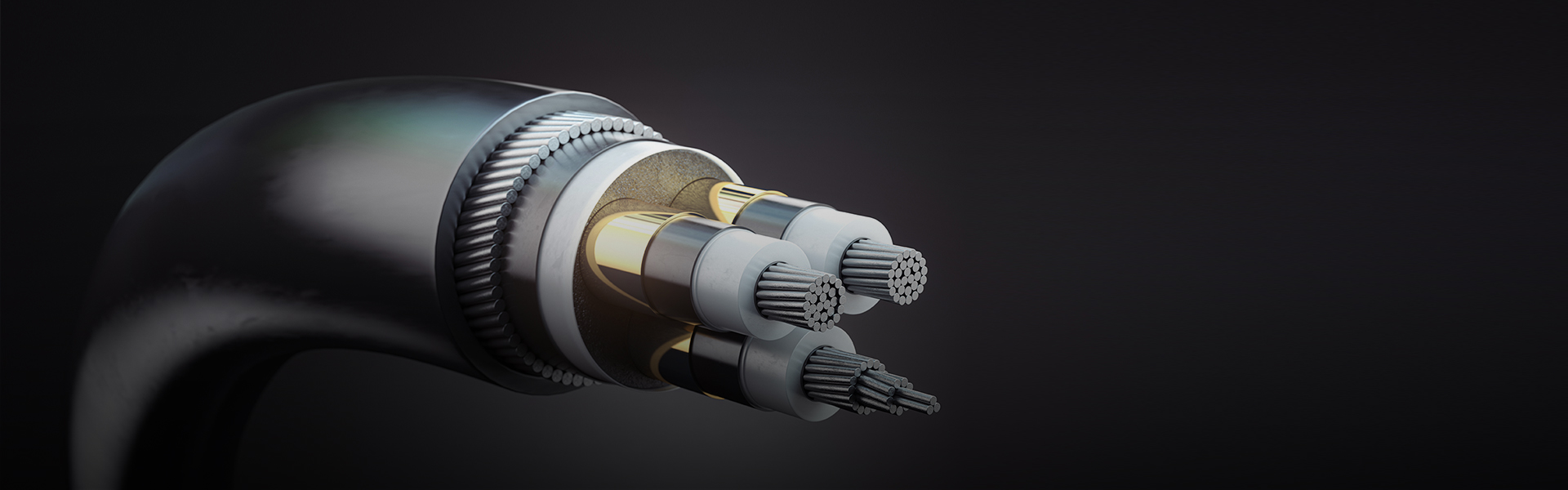
Medium-voltage aerial insulated cables (typically 10–35 kV) operate under sustained UV exposure, wide temperature cycling, and direct weather contact — conditions that place substantially greater demands on insulation material performance than the protected environment of underground or indoor cable installations. The insulation must simultaneously provide adequate dielectric strength for the voltage class, resist photodegradation and thermal oxidation over a 30–40 year service life, and maintain adequate mechanical flexibility for installation at low temperatures. These requirements point toward crosslinked polymer insulation systems rather than thermoplastic materials.
XLPE (cross-linked polyethylene) is the dominant insulation material for medium-voltage AIC due to its combination of high dielectric strength, low dielectric constant, excellent UV resistance with appropriate carbon black or UV stabilizer additives, and temperature rating of 90°C continuous/250°C short-circuit. Unlike thermoplastic PE, XLPE does not soften or flow under sustained mechanical load at elevated temperatures — a critical property for overhead cables that may operate at high temperatures under peak loading in summer. The crosslinking network prevents the dimensional changes that would otherwise occur in straight PE above its crystalline melting temperature (~125°C), maintaining insulation geometry and hence characteristic impedance under all operating conditions.
EPR (ethylene propylene rubber) is used in medium-voltage AIC for applications requiring higher flexibility at low installation temperatures or inherently superior moisture resistance. EPR-insulated AIC cables remain flexible at –40°C and can be installed and handled without risk of insulation cracking in arctic or high-altitude environments where XLPE-insulated cables become dangerously brittle. EPR's amorphous molecular structure also provides inherent resistance to water treeing without the tree-retardant additive packages required in XLPE — relevant for AIC installations in high-humidity coastal environments where moisture condensation on the insulation surface is a consistent condition. The trade-off is EPR's higher dielectric constant (2.8–3.5 vs. 2.3 for XLPE), which increases the cable's capacitive charging current — a minor consideration at medium voltage but relevant for long rural feeder lines where charging current represents a measurable fraction of thermal ampacity.
The outer jacket of medium-voltage AIC is a separate UV-stabilized black polyethylene or HDPE layer applied over the insulation. The jacket's primary functions are UV protection (carbon black at 2–3% by weight provides broad-spectrum UV absorption), mechanical protection against abrasion from branch contact, and bird beak protection — a significant issue in regions with large corvids or parrots that peck at cable insulation. Jacket hardness and wall thickness are specified to resist bird attack; some AIC specifications require a minimum jacket Shore D hardness of 50–55 and a minimum jacket wall thickness of 1.5–2.0 mm specifically to address this failure mode in susceptible geographic regions.
Comparing Low-Voltage and Medium-Voltage Aerial Insulated Cable Constructions
While both low-voltage and medium-voltage aerial insulated cables are designed for overhead outdoor service, their constructions differ fundamentally across several parameters driven by the different voltage classes, mechanical load requirements, and installation environments. Understanding these differences helps utilities and project engineers make correct specifications and avoid applying LV cable practices to MV installations or vice versa.
| Parameter | Low-Voltage AIC (0.6/1 kV) | Medium-Voltage AIC (10–35 kV) |
| Insulation Material | XLPE or PVC (0.7–1.2 mm wall) | XLPE or EPR (3.4–8.0 mm wall depending on voltage) |
| Conductor Screen | Not required | Semiconducting conductor screen required above ~6 kV U0 |
| Insulation Screen / Metallic Screen | Not required | Semiconducting insulation screen + copper wire or tape screen required |
| Conductor Material | Annealed aluminum (all-aluminum bundle); steel-reinforced neutral for self-supporting | AAAC (all-aluminum alloy conductor) or ACSR for single-core; hard-drawn aluminum alloy preferred |
| Typical Spans | 40–80 m (self-supporting); up to 100 m with dedicated messenger | 60–150 m depending on conductor size and loading zone |
| Installation Method | Bundle strung together; helical grip at supports | Single-core cables strung separately on messenger; phase spacing maintained by spacers |
| Relevant Standards | IEC 60502-1, NFC 33-209, AS/NZS 3560 | IEC 60502-2, NFC 33-032, CENELEC HD 626 |
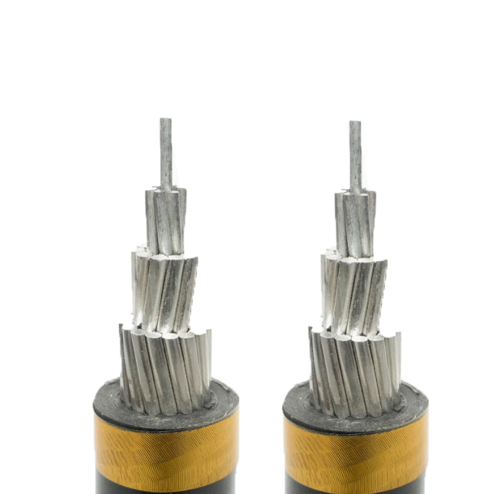
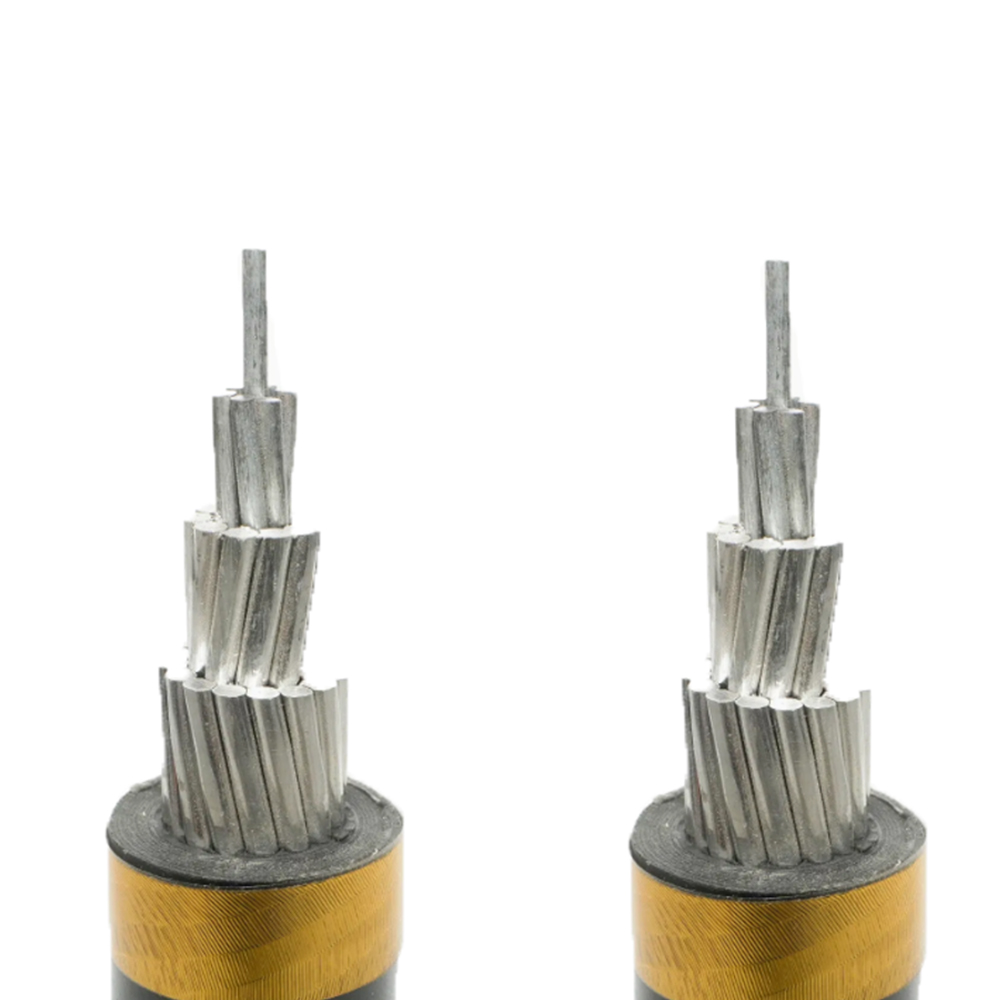
The requirement for semiconducting conductor and insulation screens in medium-voltage AIC is the most consequential construction difference and is frequently misunderstood by procurement teams familiar only with low-voltage cable specifications. Without the conductor screen, the electric field at the surface of a stranded conductor is highly non-uniform — concentrated at strand edges and surface protrusions — and partial discharge initiates at these concentration points. In a 10 kV AIC cable, the electric field gradient at an unscreened conductor surface can be 5–10 times the average field in the insulation, far exceeding the partial discharge inception threshold of XLPE. The semiconducting screen homogenizes this field by presenting a smooth, continuous equipotential surface to the insulation, reducing the peak field to near the average value. Omitting or improperly applying the conductor screen on a medium-voltage AIC cable — which cannot happen on a low-voltage cable because LV cables have no such requirement and the construction step simply does not exist — results in partial discharge-induced degradation that reduces the cable's service life from the expected 30–40 years to potentially 3–5 years.
Wind and Ice Loading Standards for Aerial Cable Mechanical Design: How Regional Climate Governs Conductor Selection
The mechanical design of aerial insulated cables — conductor alloy, cross-section, stranding design, and support hardware ratings — is governed by the maximum combined wind and ice loading the cable must withstand without permanent deformation or strand failure. Different regional standards define design loading cases based on local climate data, and selecting a cable mechanical design optimized for a temperate European climate and installing it in a high-ice-loading Canadian or Norwegian environment is a systematic design error that results in excessive sag, connector pull-out, or conductor fatigue failure within the first few years of service.
The IEC 60826 standard provides the framework for overhead line mechanical design and defines three loading reliability levels (I, II, III) corresponding to return periods of 50, 150, and 500 years for the design wind and ice event. Most distribution utility specifications use Level I or II reliability. Within the IEC framework, ice loading is characterized by the equivalent ice thickness on the conductor — typically 0 mm (ice-free), 10 mm, 20 mm, or 30 mm — combined with a simultaneous wind pressure. A 30 mm ice sleeve on a 95 mm² conductor adds approximately 2.5 kg/m of dead load to the conductor; at a 100-meter span, this corresponds to an additional 250 kg of catenary weight that the conductor and pole hardware must support. The maximum conductor tension under this condition, combined with the initial installation tension, must remain below the conductor's rated everyday tension (RET) — typically 20–25% of the conductor's rated tensile strength (RTS) for aluminum alloy conductors in distribution networks.
Wind loading on insulated aerial cables differs from wind loading on bare conductors because the larger outer diameter of an insulated cable presents a greater cross-sectional area to wind pressure. A 95 mm² bare ACSR conductor has an outer diameter of approximately 13.5 mm; the same conductor insulated with XLPE for 10 kV service may have an outer diameter of 28–32 mm, producing more than twice the wind drag force per unit length. Cable suppliers who provide mechanical specifications based on conductor cross-section without accounting for the increased aerodynamic diameter of the insulated cable assembly will systematically underestimate the design wind load, potentially resulting in cables that exceed their maximum everyday tension under design wind conditions even without ice loading. Procurement specifications should explicitly require that the mechanical design calculation accounts for the overall cable outer diameter, not just the bare conductor properties.
Conductor alloy selection interacts directly with ice loading performance through the concept of creep. Aluminum conductors under sustained tension experience time-dependent elongation (creep) that is distinct from elastic stretch — creep does not recover when the load is removed, causing permanent sag increase over the service life. Annealed aluminum (used in LV ABC conductors for flexibility) has significantly higher creep rates than hard-drawn aluminum alloy (AAAC, AAAR) under equivalent tension. In ice-prone regions where conductors periodically experience high tensions during ice loading events, the use of annealed aluminum conductors results in progressive sag increase over 10–15 years that eventually violates ground clearance requirements. Specifying hard-drawn aluminum alloy conductors with creep pre-tensioning during installation is the standard design countermeasure in regions with regular ice loading.
Jointing and Termination of Aerial Insulated Cables: Practices That Determine Long-Term Reliability
The joints and terminations of aerial insulated cables are statistically the most common locations for premature failure in aerial distribution networks. A properly manufactured cable that meets all electrical and mechanical specifications can be rendered unreliable by a single poorly executed joint or incorrect termination, and in an overhead installation, joint failures typically result in open-circuit faults that cause outages rather than the ground faults that overhead line protection relays are optimized to detect and clear quickly. Understanding the critical steps in aerial cable jointing and termination explains why specialized training and tooling are non-negotiable for these operations.
LV Aerial Bundle Cable Joints
Low-voltage ABC joints are made using piercing connectors (also called insulation-piercing connectors or IPCs) that clamp onto the insulated cable without requiring the insulation to be stripped. The connector body contains stainless steel piercing teeth that penetrate the insulation and make contact with the conductor when the connector is torqued to its specified value using a shear-head bolt — the bolt shears off at a defined torque, providing tactile confirmation that the correct contact force has been achieved and preventing over-tightening that could damage the conductor strands. The piercing connector body is self-sealing against moisture entry around the penetration points. The critical installation parameter is the shear torque — using a standard wrench and estimating torque by feel produces inconsistently terminated joints that either under-compress (high contact resistance) or over-compress (strand damage) at a high rate. IPCs must be installed with a calibrated torque wrench or the proprietary torque-limiting driver supplied by the connector manufacturer for the specific connector series.
MV Aerial Cable Joints and Terminations
Medium-voltage AIC joints and terminations require restoration of each insulation layer in the correct sequence — conductor screen, insulation, insulation screen, metallic screen, and outer jacket — using materials that are electrically and mechanically compatible with the cable's original construction. Pre-formed cold-shrink or heat-shrink joint kits from reputable manufacturers provide calibrated material volumes and assembly sequences for specific cable families. The most critical step is the preparation of the insulation screen at the joint interface: the transition from screened to unscreened insulation must be smooth and gradual (typically a penciled taper of 15–25 mm length) to prevent field concentration at the screen cutback. An abrupt screen cutback — caused by using cutting tools that score the insulation surface or failing to taper the semiconductor layer — creates a triple point (conductor screen, insulation, and surrounding air meet at a single geometric point) where the electric field concentration can be 10–20 times the average field in the insulation, initiating partial discharge at operating voltage even when the rest of the joint is correctly assembled.
Outdoor terminations on MV AIC are subject to tracking — the formation of conductive carbon paths along the insulation surface caused by pollution deposition combined with periodic wetting. Tracking develops progressively: dry band arcing at the boundaries of wet and dry zones on the insulation surface generates sufficient energy to carbonize the insulation surface locally, and repeated arcing cycles extend the carbon path toward the energized conductor over months or years. The standard countermeasure is the use of heat-shrink or cold-shrink outdoor termination kits that incorporate a high-tracking-resistance silicone rubber weather shed — a series of umbrella-shaped ribs that increase the leakage path length between the energized conductor and the grounded metallic screen, and shed rain to prevent continuous wet contamination layers from forming. In high-pollution environments (coastal areas, industrial zones, desert regions with alkaline dust), the required creepage distance per kV of rated voltage increases beyond the standard IEC 60071 specification, requiring either longer shed terminations or anti-pollution silicone grease treatment of the weather sheds.
Fault Detection and Protection Coordination Differences Between Bare Overhead Lines and Aerial Insulated Cable Networks
Converting a distribution network from bare overhead conductors to aerial insulated cables changes the fault behavior of the network in ways that require corresponding changes to protection relay settings, recloser operation sequences, and fault detection philosophy. Utilities that install AIC without reviewing and adjusting protection coordination frequently experience periods of either missed fault detection (protection that fails to trip for high-impedance faults that insulation delays) or nuisance operation (protection that misinterprets insulation-limited transient faults as permanent faults requiring lockout).
The most significant change is the behavior of conductor-to-conductor and conductor-to-tree contact faults. On a bare overhead line, a phase-to-phase contact from wind-induced galloping or from a fallen tree branch creates a bolted fault with very low impedance — typically less than 1 Ω arc resistance — producing fault currents that are readily detected by overcurrent elements in milliseconds. On an insulated aerial cable, the same contact creates a fault current that must flow through the insulation resistance and capacitance of the cable rather than directly between conductors. For a fresh contact through undamaged insulation, the fault current may be only a few amperes — below the pickup threshold of overcurrent relays calibrated for bare conductor faults. The insulation degrades progressively under the sustained electrical stress, and the fault current increases over minutes to hours until it reaches the relay pickup threshold. This delayed fault development means that a fault that would have been cleared in 0.3 seconds on a bare conductor network may take 30–90 minutes to develop to a level that trips the relay on an insulated cable network — potentially causing sustained insulation degradation, cable heating, and fire ignition in dry vegetation where the cable rests.
The appropriate protection philosophy change for AIC networks involves supplementing standard overcurrent protection with earth fault protection sensitive enough to detect the low-level fault currents produced by insulation-limited contact faults. Sensitive earth fault (SEF) relays with pickup thresholds of 1–5 A (compared to 10–50 A for standard earth fault protection on bare conductor networks) can detect the initial leakage current through damaged insulation and trip the feeder before the fault develops to the point of full insulation breakdown. The trade-off is increased sensitivity to normal system imbalance and harmonic currents, which requires careful SEF relay threshold setting and time delay coordination to avoid nuisance tripping from load unbalance in rural networks with long single-phase tapped laterals. Neutral earthing of the medium-voltage network — whether effectively earthed, resonant earthed (Petersen coil), or isolated neutral — determines both the magnitude of earth fault currents and the appropriate SEF relay sensitivity, making protection philosophy review inseparable from the earthing system configuration when transitioning from bare to insulated aerial distribution.