

 English
 Español
 عربى
عربى
 русский

Industry knowledge
Pair Count and Gauge Selection: Why Getting These Wrong Is Costly
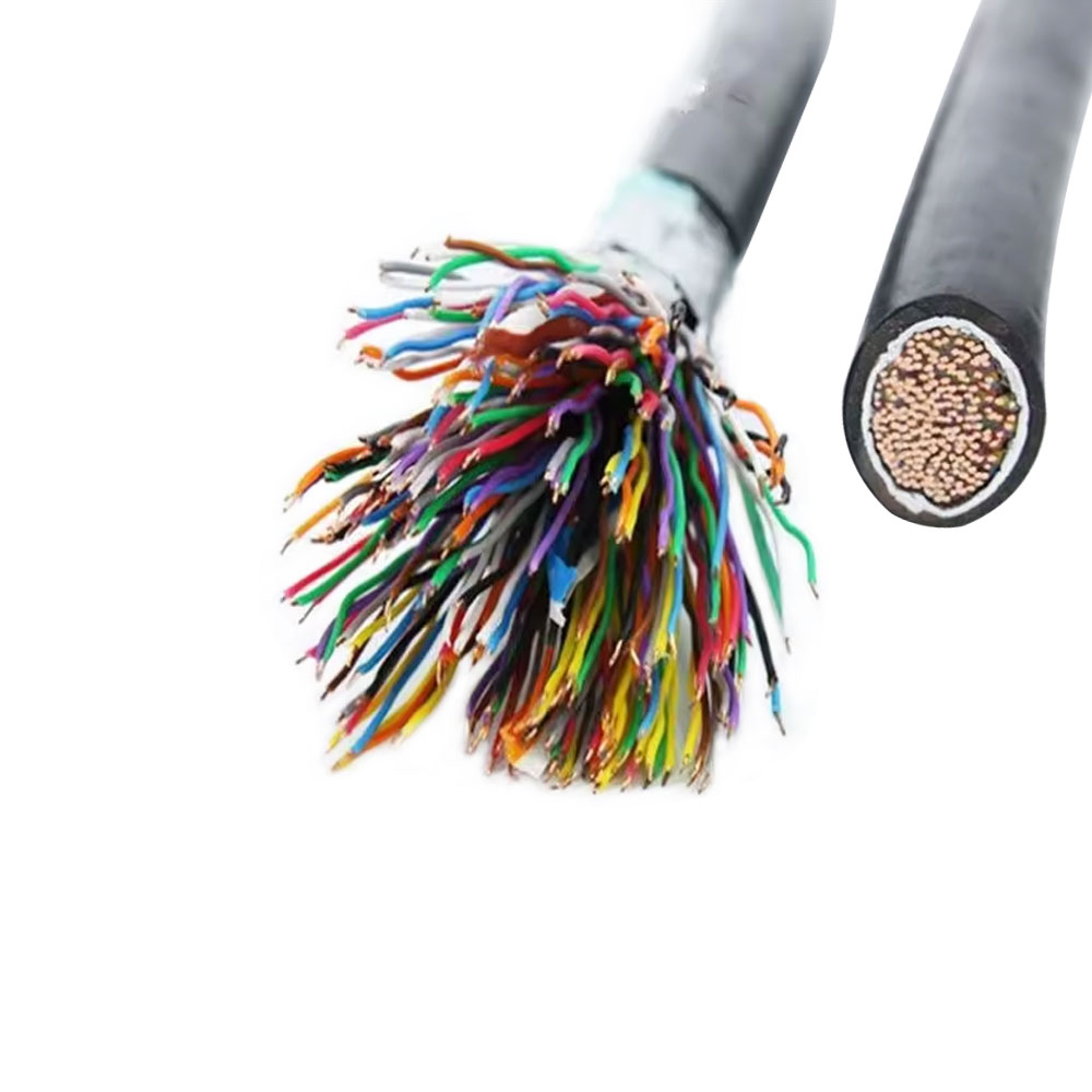
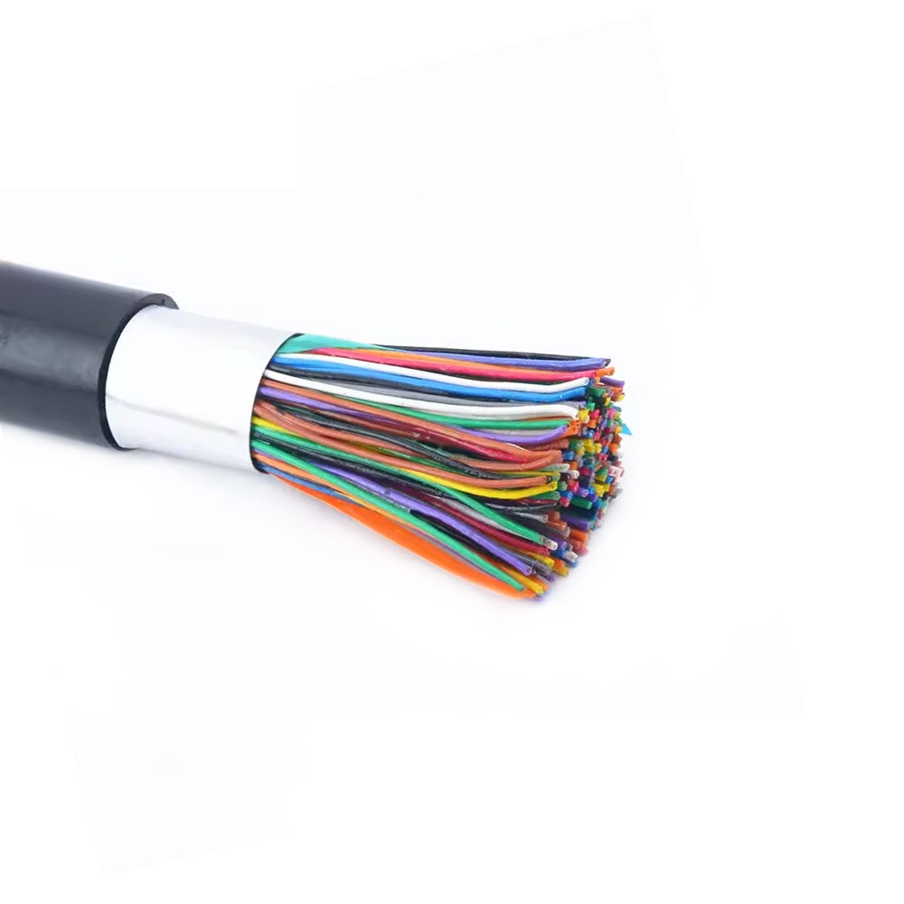
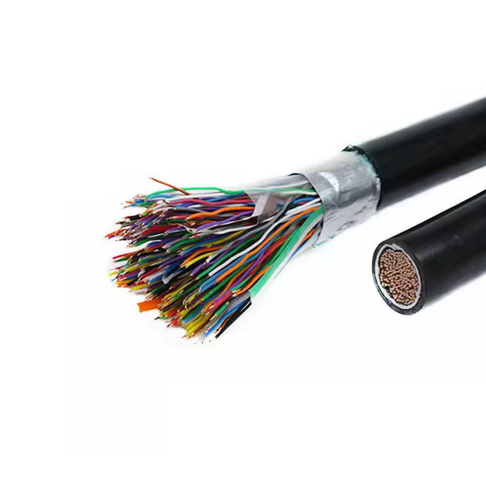
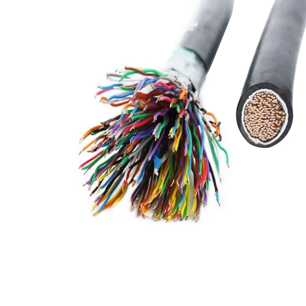
Urban communication cables are specified primarily by two parameters: the number of twisted pairs and the conductor gauge (AWG or mm²). In practice, both are frequently under-specified during network planning, leading to costly re-pulls or parallel cable runs within years of installation. A 100-pair cable installed for a residential block may seem sufficient at commissioning, but as fiber-to-the-building deployments push VDSL2 and G.fast aggregation equipment closer to end users, active pair demand in the last-mile copper segment can spike unexpectedly as pair-bonding and backup circuits are added.
Conductor gauge affects both loop resistance and crosstalk behavior. Thinner conductors (0.32 mm or 26 AWG) reduce cable weight and duct space but raise DC loop resistance, which limits the effective range of DSL technologies — particularly significant in areas where cabinet-to-premise distances exceed 300 meters. Thicker conductors (0.5 mm or 0.6 mm) extend usable loop length and reduce insertion loss, making them the preferred choice for longer underground runs in suburban communication networks. For backbone feeder cables serving multiple distribution points, 0.5 mm conductor diameter is the practical minimum to maintain adequate transmission margins across the full frequency range used by modern broadband technologies.
Anhui Zhishang Cable Technology Co., Ltd. applies this understanding by offering a structured range of pair counts — from 5-pair local distribution cables up to 2,400-pair trunk cables — with gauge options matched to the typical span distances and service densities found in urban and suburban network topologies.
How Insulation and Sheathing Materials Determine Underground Durability
The underground environment imposes chemical and mechanical stresses on communication cables that are rarely visible until failures emerge. Soil pH, groundwater salinity, the presence of hydrocarbons from road runoff, and freeze-thaw cycles all attack cable construction from the outside in. For urban communication cables, the outer sheath material is the primary barrier, and the choice between PE (polyethylene), PVC, and double-jacketed PE/steel tape constructions has long-term consequences that extend well beyond initial cost.
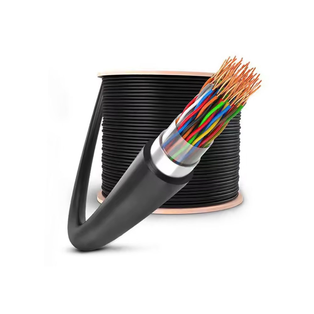
High-density polyethylene (HDPE) sheaths offer superior resistance to moisture ingress, soil acids, and microbial degradation. HDPE does not plasticize over time the way PVC does, which means it maintains its original mechanical properties over decades of burial — a meaningful advantage given that urban communication cables are expected to remain in service for 20 to 40 years without excavation. PVC remains common in indoor or semi-protected installations due to its lower cost and easier termination, but it is not the appropriate choice for direct-burial or duct-routed cables in environments with high moisture or chemical exposure.
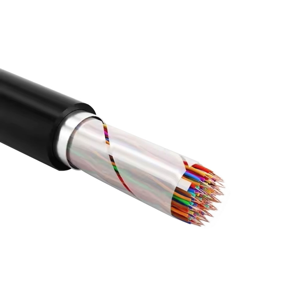
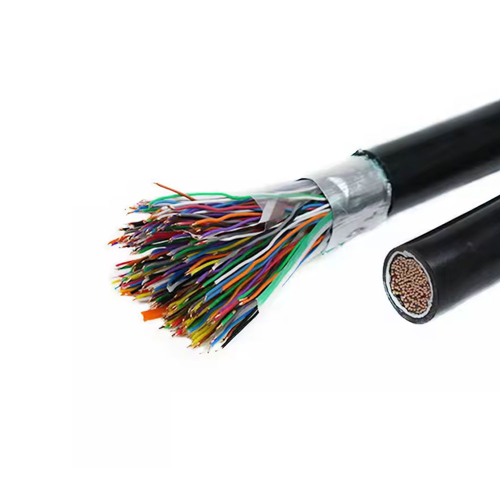
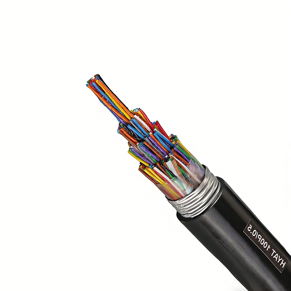
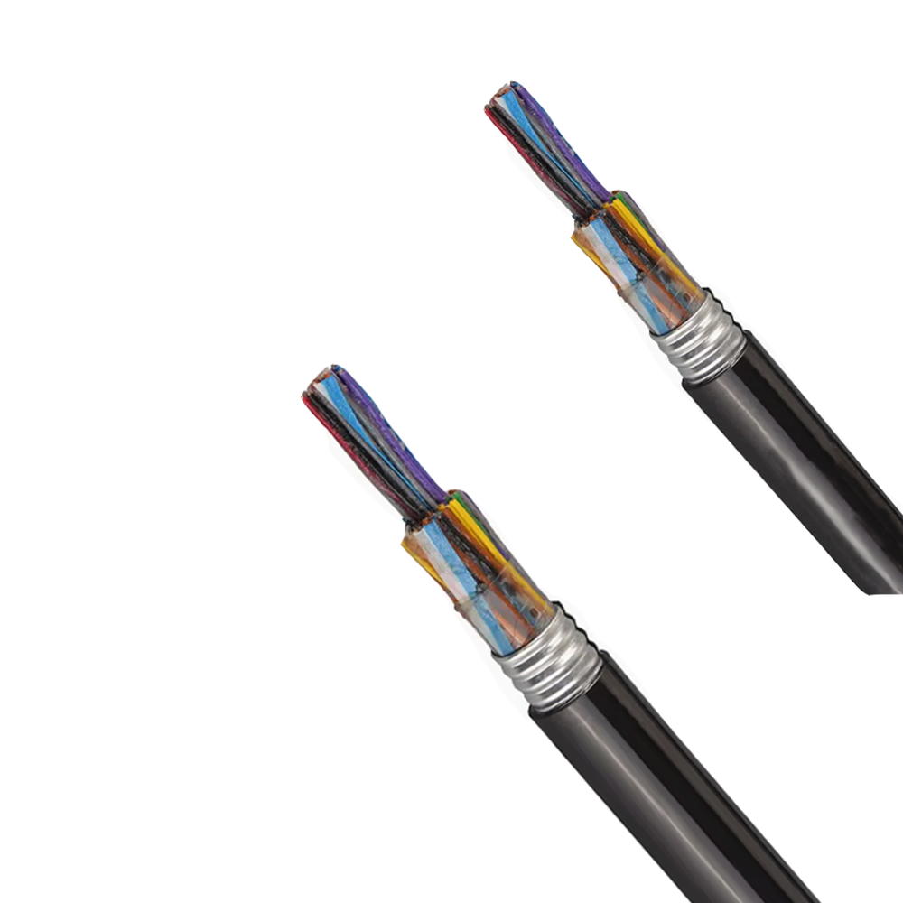
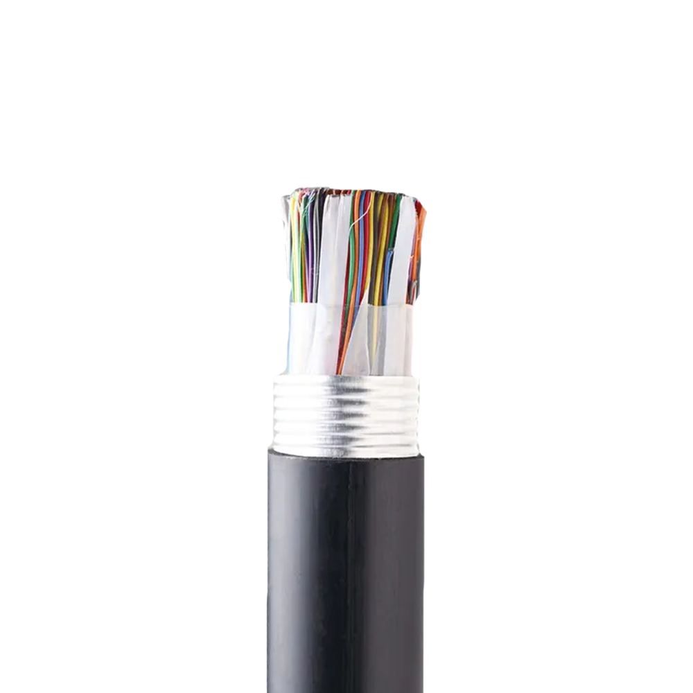
For cables in areas with high rodent activity or routes beneath roads and railways where mechanical damage risk is elevated, an additional armoring layer — typically corrugated steel tape or steel wire — is added beneath the outer jacket. This construction does not make the cable watertight on its own; the quality and continuity of the flooding compound filling the interstices between pairs is equally critical. A poorly applied flooding compound leaves air pockets that trap moisture, which migrates longitudinally along the cable and causes insulation resistance degradation across a long cable section from a single point of jacket damage.
Common Underground Sheathing Constructions Compared
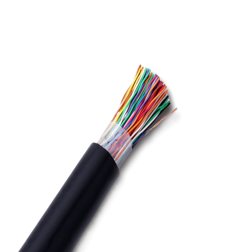
- PE single sheath: Standard for duct installation; good moisture resistance; not suitable for direct burial in aggressive soils without additional protection.
- PE + corrugated steel tape + PE: Preferred for direct burial; combines mechanical protection with moisture barrier; adds weight and reduces flexibility.
- PE + steel wire armoring: Used where tensile loads are expected (steep terrain, bridge attachments, or vertical risers); individual wires provide both protection and pulling strength.
- Gel-filled (flooded) core: Flooding compound fills all air spaces between pairs; essential for splice-point moisture resistance and longitudinal water blocking.
Crosstalk Management in High-Density Urban Cable Bundles
As more broadband traffic is pushed over copper pairs using vectoring and G.fast technology, crosstalk — both near-end (NEXT) and far-end (FEXT) — becomes a binding constraint on achievable throughput per pair. Urban communication cables that were designed and installed for voice-grade POTS service often exhibit crosstalk levels that are acceptable at audio frequencies but severely limit performance above 10 MHz. Understanding the physical mechanisms behind crosstalk helps in evaluating whether an existing cable plant can support broadband upgrades or must be replaced.
Crosstalk between pairs in a multi-pair cable is primarily determined by the precision and consistency of the twist pitch (the number of twists per unit length) for each pair. Each pair in a well-manufactured urban communication cable has a unique, carefully controlled twist pitch to minimize coupling with adjacent pairs. When twist pitches are inconsistent — either from manufacturing variation or physical damage during installation — capacitive and inductive imbalance between pairs increases, raising the noise floor across the entire cable bundle. This is why cable manufacturer process control during twisting is not merely a quality checkbox but has a direct impact on the broadband capacity of the deployed network.
In vectored VDSL2 and G.fast deployments, the DSLAM or DPU (Distribution Point Unit) applies active digital signal processing to cancel crosstalk between pairs in the same binder group. This vectoring only works effectively when the cable's crosstalk coupling characteristics are stable and predictable — which requires consistent physical construction throughout the cable's length. Cables with splice points that disturb the original pair geometry, or sections where pairs have been re-bundled incorrectly after a repair, create crosstalk anomalies that degrade vectoring gain and reduce per-pair throughput across the entire group. Zhishang Cable maintains strict twist-pitch tolerances and performs electrical balance testing on production batches to support these demanding deployment scenarios.
| Technology | Frequency Range | Crosstalk Sensitivity | Cable Requirement |
|---|---|---|---|
| POTS / ISDN | Up to 4 kHz | Low | Standard twist pitch |
| ADSL2+ | Up to 2.2 MHz | Moderate | Controlled twist pitch per pair |
| VDSL2 (vectored) | Up to 17 / 35 MHz | High | Tight pitch tolerance + balance testing |
| G.fast | Up to 106 / 212 MHz | Very High | Premium construction, stable binder grouping |
Duct Space Planning and Cable Diameter: A Constraint Often Ignored Until It Becomes a Problem
Urban communication infrastructure is built to last decades, but duct networks — the conduits through which cables are pulled — are sized based on assumptions made at the time of construction. When those ducts fill up, adding capacity requires either micro-trenching to install new ducts (disruptive and expensive in paved urban environments) or replacing large-diameter cables with higher-density alternatives. For network operators and infrastructure planners, understanding how cable outer diameter relates to duct fill ratio is a practical tool for maximizing future capacity without over-engineering the initial installation.
Standard duct fill practice limits occupied cross-sectional area to 40–50% of the inner duct area for a single cable, and proportionally less when multiple cables share a duct. This margin is not waste — it accounts for the bending forces required during pulling, thermal expansion of the cable over its service life, and the clearance needed if the cable must ever be replaced without excavating the entire route. A cable with an outer diameter only 10% larger than planned can reduce the theoretical remaining capacity of a duct by significantly more than 10%, because the constraint is area (proportional to diameter squared), not linear dimension.
The shift from traditional paper-insulated lead-sheathed (PILS) cables to modern PE-insulated cables with filled cores has already reduced cable diameters substantially for equivalent pair counts. Further diameter reduction is achievable by using tighter core geometry, thinner insulation wall thicknesses compliant with current standards, and optimized binder tape or screen constructions. For network planners working with constrained duct infrastructure, specifying cables from manufacturers like Anhui Zhishang Cable Technology Co., Ltd. that publish detailed dimensional data and offer compact-construction variants allows accurate duct fill calculations before cable procurement — rather than discovering a mismatch during installation.