
Get more content that can help you
Content
A computer encoder cable — sometimes called a servo feedback cable or encoder-specific cable — is a highly engineered transmission line designed to carry precise position and speed feedback signals from rotary or linear encoders to motion controllers, PLCs, and servo drives. Unlike standard data cables, encoder cables must handle fast, weak differential pulse signals (such as A/A−, B/B−, Z/Z−) with near-zero distortion, all while operating in electrically noisy industrial environments where inverters, motor drivers, and heavy machinery generate intense electromagnetic interference.
In any closed-loop motion control system, the encoder is the system's eyes — it tells the controller exactly where a moving component is and how fast it is traveling. If the cable carrying that feedback signal introduces noise, attenuation, or delay, the controller makes decisions based on corrupted data, which directly degrades positioning accuracy, response speed, and operational stability. In high-throughput industries like semiconductor fabrication or CNC machining, even a micron-level positioning error can result in defective products or costly downtime. The encoder cable is therefore not a peripheral accessory — it is a precision component that determines the ceiling of the entire system's performance.
Computer encoder cables serve a wide range of demanding applications, all sharing a common requirement: high-fidelity, real-time feedback over signal lines that may be subject to continuous motion, mechanical stress, and electromagnetic pollution. Below are the most common deployment environments:
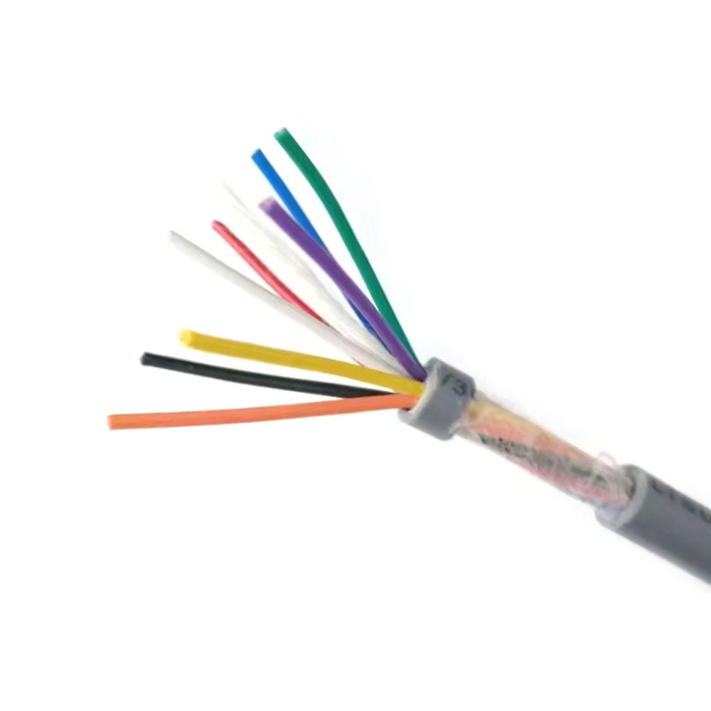
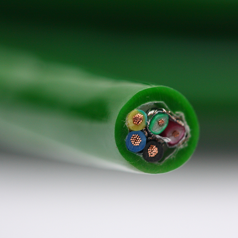
Understanding the internal construction of an encoder cable explains why it performs so differently from a generic multi-conductor cable. Each layer serves a specific engineering purpose.
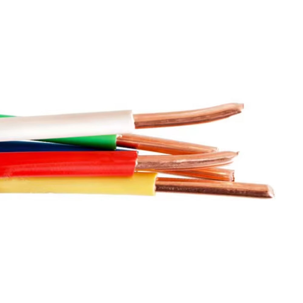
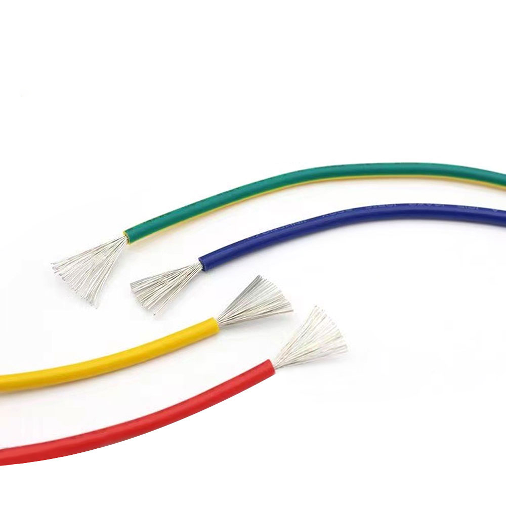
The conductors are made from ultra-fine, oxygen-free copper (OFC) strands arranged in a multi-strand twisted bundle. This construction delivers low DC resistance, high flexibility, and superior resistance to flex fatigue compared to solid or coarsely stranded wire. The insulation layer uses low-dielectric-constant materials such as special polyethylene (PE) or foamed PE, which minimizes inter-conductor capacitance. High capacitance is the primary enemy of high-frequency digital signals: it rounds off pulse edges, increases signal rise time, and limits the maximum usable transmission distance and frequency.
Encoder signals are transmitted as differential pairs (e.g., A and A−). Each pair is twisted at a precisely controlled, equal pitch. This equal-twist geometry is critical: any variation in twist pitch breaks the electrical symmetry between the two conductors in a pair, reducing common-mode noise rejection and allowing interference to corrupt the signal. High-quality encoder cables maintain tight pitch tolerances (often ±5% or better) along the entire cable length.
Shielding is one of the most important differentiators between encoder cables and standard cables. Premium encoder cables typically use a composite shielding approach:
Aramid fibers (such as Kevlar) are incorporated as central reinforcing members or as gap fillers between twisted pairs. These fibers absorb tensile stress during bending and pulling, protecting the delicate signal conductors from mechanical damage. The outer sheath is extruded from specially formulated compounds chosen to match the deployment environment. The three most common sheath materials for encoder cables are:
| Material | Key Properties | Best For |
| High-Elasticity PVC | Cost-effective, good flexibility at moderate temperatures | General industrial use, lower flex cycles |
| PUR (Polyurethane) | Excellent oil resistance, abrasion resistance, high flex life | Drag chains, robot arms, machining environments |
| TPE (Thermoplastic Elastomer) | Wide temperature range, UV resistance, halogen-free options | Outdoor systems, food processing, extreme temperatures |
Choosing the correct encoder cable requires matching the cable's electrical and mechanical specifications to both the encoder's output characteristics and the physical demands of the installation. Working through the following parameters systematically will prevent mismatches that lead to signal errors or premature cable failure.
Incremental encoders output simple pulse trains (A, B, Z channels), while absolute encoders — especially multi-turn variants — may use serial protocols such as EnDat, BiSS-C, HIPERFACE, or SSI. Serial protocol cables must support higher bandwidth and often require tighter impedance control (typically 100–120 Ω differential) than basic incremental encoder cables. Confirm with the encoder datasheet which protocol is in use before specifying the cable.
Signal attenuation increases with both cable length and signal frequency. For high-resolution encoders operating at pulse frequencies above 1 MHz, cable capacitance becomes a critical limiting factor. As a practical rule, keep total line capacitance (pF/m × meters) within the drive manufacturer's specified limit. When longer runs are unavoidable, choose cables with the lowest possible capacitance per meter and consider adding line drivers at the encoder output.
Static installations (cables that do not move after commissioning) allow larger bend radii and longer flex life is not a priority. Dynamic installations — drag chains, robot joints, linear slides — require cables rated for a minimum bend radius as low as 5× the cable outer diameter and flex life exceeding 10 million cycles. Always specify flex-rated (also called "highly flexible" or "continuous-flex") encoder cables for any moving application.
Assess the operating environment before finalizing the sheath material: oil mist or cutting fluid exposure requires PUR; UV radiation or extreme temperatures call for TPE; food-grade or cleanroom environments may need special low-outgassing compounds. Also consider whether the cable must be flame-retardant or halogen-free to meet building or machinery safety codes.
A reliable encoder cable supplier applies rigorous quality control throughout the manufacturing process and validates performance through both 100% production testing and statistical sample testing. Key tests include:
Products that conform to recognized standards — such as UL, CE, RoHS, or sector-specific certifications — provide additional assurance that the cable meets defined safety and performance benchmarks.
It is worth emphasizing how directly cable quality propagates through a motion control system. A high-capacitance cable slows pulse edge transitions, causing the controller to miscount encoder pulses at high speeds — a phenomenon known as missed counts or count loss — which manifests as position drift and velocity ripple. A poorly shielded cable picks up inverter switching noise, injecting false pulses that the controller interprets as real encoder movement, causing unexpected axis oscillation or fault trips. A mechanically inadequate cable fails internally during continuous flex, producing intermittent open circuits that are exceptionally difficult to diagnose because they may only appear during specific positions in the machine's motion profile.
Conversely, a properly specified computer encoder cable with low capacitance, high shielding effectiveness, precise pair-twist symmetry, and adequate flex life directly translates into tighter position loop bandwidth, faster servo tuning, higher throughput, and significantly reduced unplanned downtime. In high-value manufacturing processes, the return on investing in the correct encoder cable far exceeds its incremental cost over a generic alternative.
When evaluating encoder cable suppliers, always request high-frequency test reports alongside mechanical flex-life data, and verify that the offered cable matches your encoder's signal protocol, transmission frequency, environmental exposure, and dynamic requirements. The right cable is not simply a wire — it is a precision signal pathway that your entire motion control system depends on every millisecond of operation.

We firmly believe that good cables are not only a competition of materials, but also a reflection of craftsmanship, quality, and responsibility.

Links
Product
Send Inquiry
No. 29 Sankeshu Road, Xuanzhou District, Xuancheng City, Anhui Province, China
+86-18621104555/+86-563-2622999
 Electrical Cable Manufacturer
OEM/ODM Wire and Cable Solutions
Electrical Cable Manufacturer
OEM/ODM Wire and Cable Solutions
 English
 Español
 عربى
عربى
 русский