

Get more content that can help you
Content
“LVDS” is one of those acronyms that turns up everywhere in datasheets, service manuals and wiring diagrams, yet it is rarely explained in plain language. If you have ever opened a display assembly or a machine-vision camera and found a flat ribbon built from tiny twisted pairs feeding a slim connector, you have already met it. This short guide unpacks what the letters mean, why the technique has lasted so long, and what it asks of the cable doing the actual work.
LVDS stands for Low-Voltage Differential Signaling. It is an electrical standard — usually cited as TIA/EIA-644 — that describes how binary data is driven onto a copper pair using a very small voltage difference. Each of the three words carries real meaning.
The driver swings only around 350 millivolts, sitting on a common-mode level near 1.2 volts. Compared with a 3.3 V or 5 V single-ended signal, that is a whisper rather than a shout, and it is the reason the interface consumes so little power at speed.
Every bit travels on two conductors carrying complementary versions of the same signal. The receiver looks only at the difference between them, not at either line against ground. This is what gives the technique its noise tolerance.
Note the last word carefully. LVDS defines electrical behavior at the physical layer, not a protocol. It says nothing about packet structure, addressing or error handling. Higher-level formats — display links, camera interfaces, board-to-board data paths — sit on top of it and give the bits their meaning.
The easiest way to grasp LVDS is to compare it with the ordinary single-ended signaling most hobbyists meet first. In a single-ended link, one wire carries the voltage and ground provides the reference. Any noise that couples onto the wire, or any shift in the ground potential between the two ends, is added straight to the signal. In a differential link, noise couples onto both conductors almost equally, so it appears as a common-mode shift that the receiver subtracts away.
| Characteristic | Single-ended | Differential (LVDS) |
|---|---|---|
| Conductors per signal | One, plus a ground return | Two, driven as a matched pair |
| Voltage swing | Rail to rail, often 3.3 V or 5 V | Roughly 350 mV around a 1.2 V common mode |
| Noise behavior | Ground noise adds directly to the signal | Common-mode noise largely cancels at the receiver |
| Power at high data rates | Climbs quickly with frequency | Stays modest because the swing is small |
| Typical use | Short, low-speed board-level links | High-speed links between boards, modules and displays |
Over the years we have watched LVDS survive wave after wave of newer interfaces, and the reasons are practical rather than fashionable:
Most links fall into one of three shapes. A point-to-point connection joins one driver to one receiver and is by far the most common. A multi-drop arrangement shares one driver across several receivers, which suits clock distribution. A multipoint version, sometimes written M-LVDS, allows several drivers and receivers to share a bus with stricter drive requirements and controlled contention. Choosing the wrong topology is one of the quiet causes of intermittent link failures.
The interface is more familiar than its name suggests. It carries video inside LCD televisions and monitors, linking the main board to the timing controller. It appears in industrial cameras, medical imaging carts, test instruments and automotive display harnesses. On production lines it stitches together control boards inside robots and CNC equipment, where engineers rely on it to move encoder and sensor data without picking up electrical interference. In automation cabinets, that reliability is precisely what keeps a line running.
Here is the part that matters to anyone specifying a harness: the standard is only half the story. A small differential swing depends heavily on the transmission medium behaving predictably. If the pair is not built to a controlled impedance, or if one conductor is slightly longer than its partner, reflections and timing errors creep in and the receiver starts making mistakes.
Intra-pair skew is the silent culprit. When the two conductors of a pair differ in length by even a few millimeters, the two halves of each bit arrive at slightly different moments, and the difference the receiver measures gets smeared. Shielding addresses the other half of the problem, keeping motor drive noise and radio-frequency interference away from a signal that has very little margin to spare.
For fixed installations inside cabinets, a foil-shielded, twisted-pair construction with a stable impedance is usually enough. Where the cable rides on a moving axis, fine-stranded conductors and a jacket that resists repeated flexing become just as important as the electrical values.
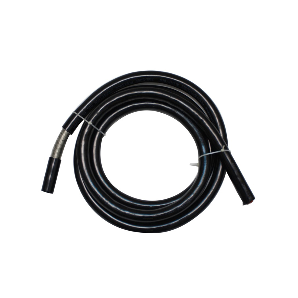 DJYPVP Shielded Twisted-Pair Computer Cable for Fixed and Moving InstallationsDouble-layer shielded twisted-pair construction with fine-stranded conductors and a moisture- and wear-resistant sheath supports stable signal transmission in cabinets and mild industrial environments.View Product →
| Parameter | Typical target | Why it matters |
|---|---|---|
| Differential impedance | 100 Ω nominal | Keeps reflections small so the signal eye stays open |
| Intra-pair skew | A few tens of picoseconds | Both edges must arrive together or the difference blurs |
| Shielding | Foil, braid, or both in noisy plants | Protects a small swing from drives and inverters |
| Conductor construction | Fine-stranded copper on moving axes | Continuous flexing eventually breaks solid cores |
| Jacket material | PVC for fixed runs, PUR for constant motion | Determines service life in the field |
We have written before about what determines the transmission stability of high-performance computer cables, and the same physics applies here almost word for word.
A shielded computer cable with individually screened pairs is the natural starting point for board-to-board and instrument links, because the construction keeps crosstalk between neighbouring pairs under control. Where the data rides alongside industrial Ethernet or bus traffic in the same duct, a cable with consistent impedance across its whole length avoids nasty surprises during commissioning.
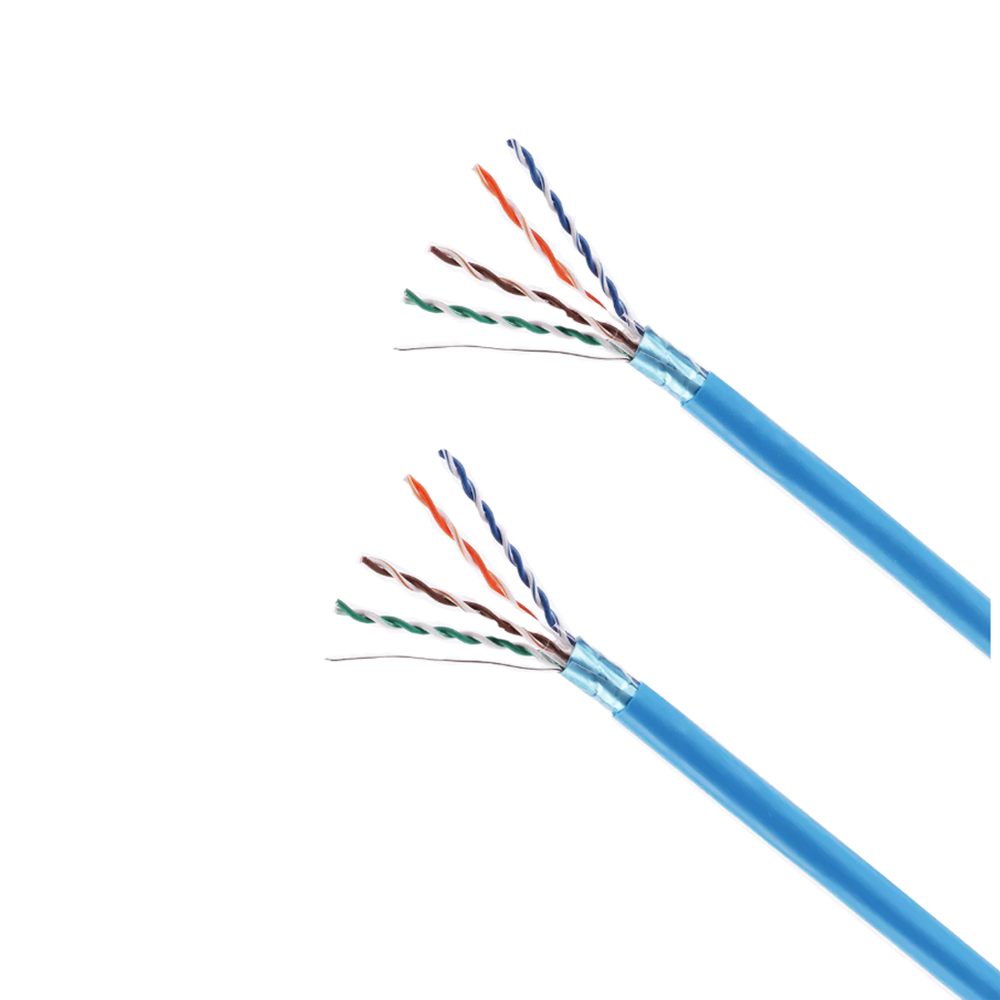 Cat6 Industrial Ethernet Bus Cable with Double-Layer ShieldingFour-pair Cat6 construction with individually shielded pairs and foil-plus-braid overall shielding supports Gigabit Ethernet and short-distance 10 Gigabit transmission in harsh industrial settings.View Product →
Encoder and resolver feedback is another place where these principles bite. A differential pair that performs perfectly on the bench can fail on a machine tool once the spindle drive starts switching, which is why screened constructions with a dedicated drain wire are so common in that role.
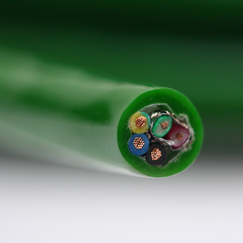 High Anti-Interference Encoder Cable for Industrial Motion FeedbackMulti-layer shielding, stable characteristic impedance and torsion-resistant PUR sheathing help preserve weak encoder signals against EMI/RFI in CNC, robotics and automated production lines.View Product →
If you are still mapping out the wider system, our automation solutions overview shows how signal, control and power cabling are typically separated across a modern production cell.
When a customer asks us to quote for an LVDS-style link, these are the questions we work through first:
No. It is an electrical layer specification. The framing, encoding and error handling come from whatever protocol is layered on top.
Sometimes, at short distances in quiet environments. For anything production-grade, a cable with controlled impedance and known skew is the safer choice.
Typically a few metres over copper, depending on data rate and cable quality. Longer runs usually call for a different physical layer or a repeater.
Very much so. Its combination of low power, low emission and simplicity keeps it in displays, cameras and industrial equipment that will be serviced for many years to come.
So the next time a drawing lists an LVDS pair, you will know exactly what it is asking for: a small, fast, noise-tolerant difference between two conductors, and a cable engineered well enough to preserve that difference from one end of the machine to the other. Get the cable right and the interface quietly does its job for years.
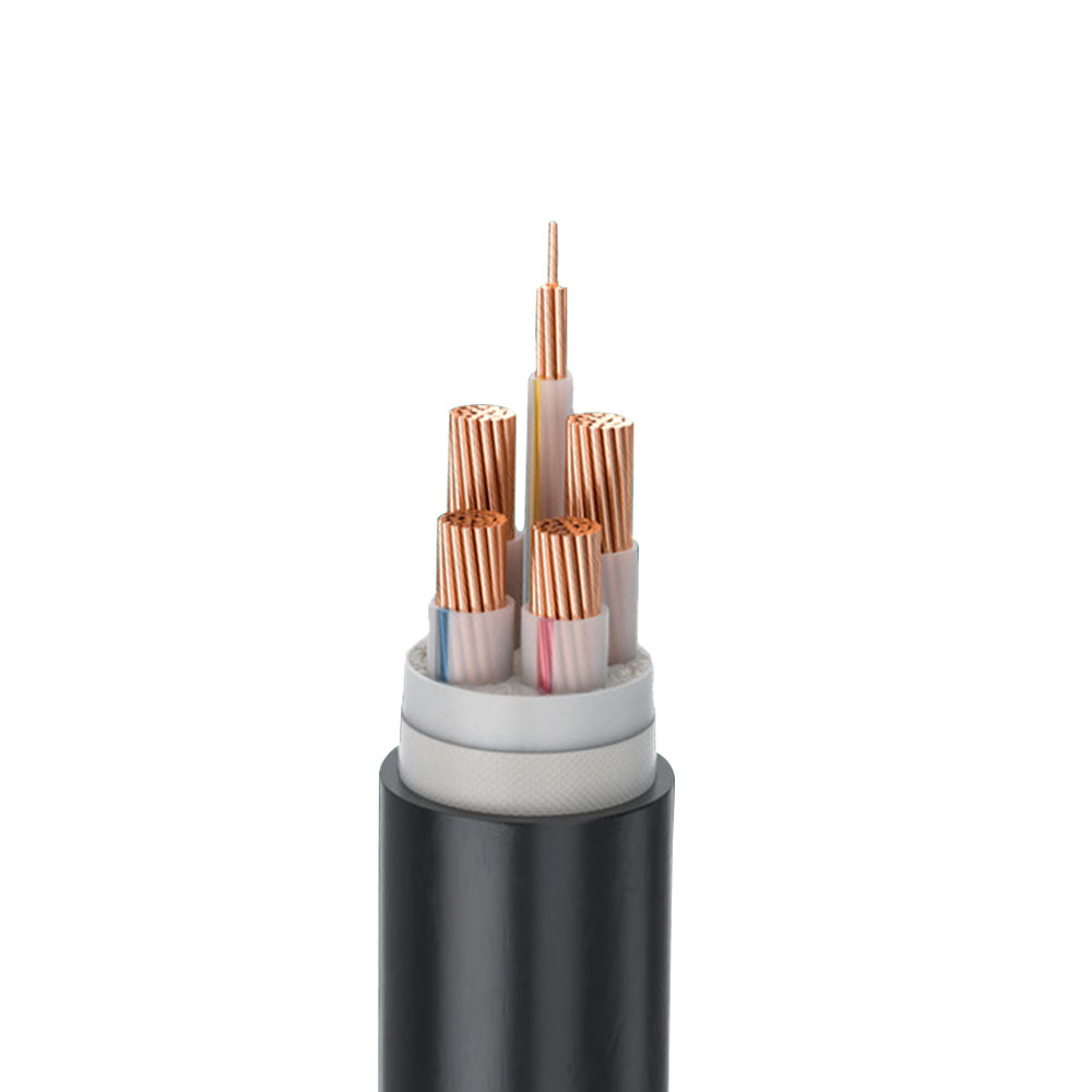
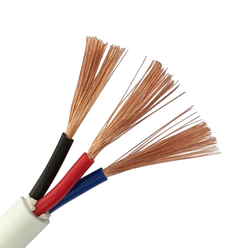
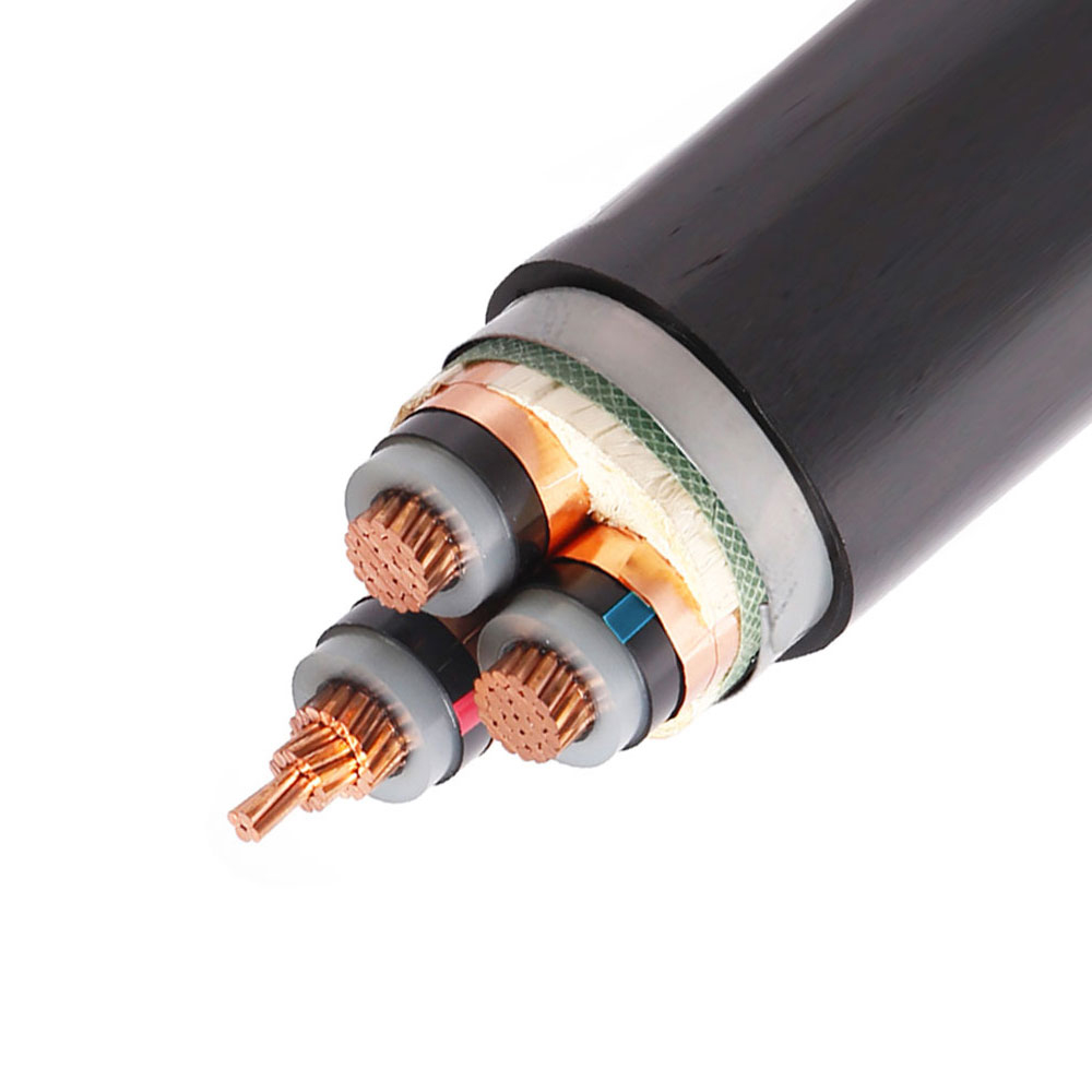
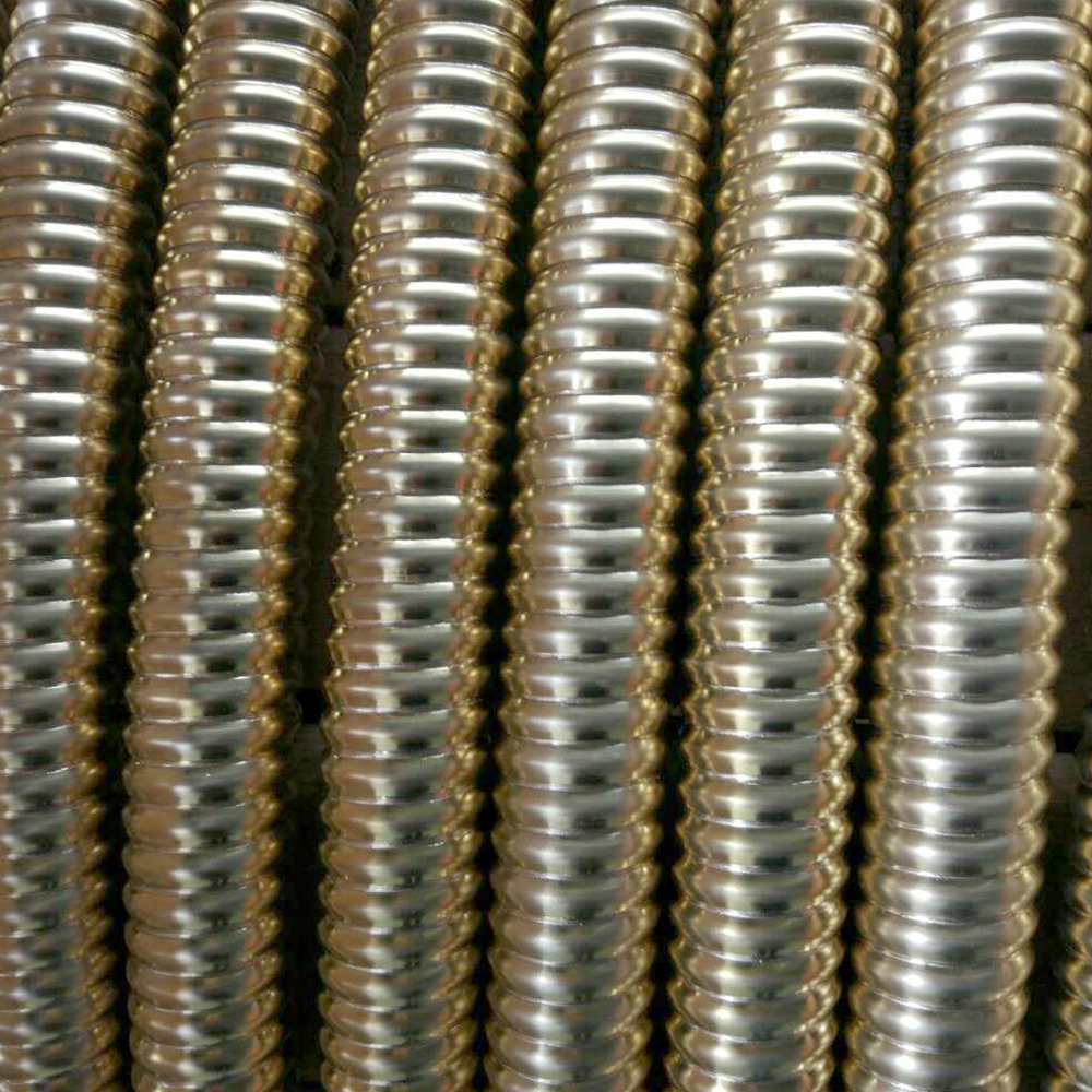
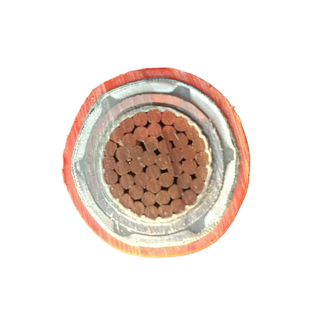

We firmly believe that good cables are not only a competition of materials, but also a reflection of craftsmanship, quality, and responsibility.

Links
Product
Send Inquiry
No. 29 Sankeshu Road, Xuanzhou District, Xuancheng City, Anhui Province, China
+86-18621104555/+86-563-2622999
 Electrical Cable Manufacturer
OEM/ODM Wire and Cable Solutions
 English
 Español
 عربى
 русский