
Get more content that can help you
Content
Ask ten people what cable impedance means and you will usually get ten slightly different versions of "resistance." It is an easy mix-up, and it costs people real time. A technician puts a multimeter across a 50 Ω coaxial cable, reads a fraction of an ohm, and concludes the reel is faulty. The reel is fine. Impedance is simply not something a multimeter can see.
We build cable for a living — everything from building wire and low-voltage power cable to shielded bus, encoder, and drag-chain cable — and questions about impedance come up most often on the signal side of that range. What follows is the explanation we tend to give on the phone, written down properly.
Impedance is the total opposition a cable presents to an alternating signal travelling along it: resistance, capacitance, and inductance acting together, and all three change with frequency. On a line that is long relative to the signal's wavelength, those effects settle into a stable ratio known as characteristic impedance, usually written Z0. For a lossless line it works out to the square root of inductance per unit length divided by capacitance per unit length.
Because both quantities are measured per unit length, characteristic impedance does not depend on how long the cable is. Ten metres and one hundred metres of the same coaxial design both sit at roughly 50 Ω. That is the part that surprises people most, and it is the reason a resistance reading tells you nothing useful about impedance.
What Z0 really comes from is geometry and materials: the diameter of the conductor, the thickness of the dielectric wall, the permittivity of that dielectric, and the spacing between the conductor and its return path. Change any one of those and the impedance moves. This is why impedance is fixed at the design stage rather than adjusted on site.
When the driver, the cable, and the receiver share the same impedance, energy moves down the line with very little reflection. Break that chain and part of the signal bounces back. On a digital link that shows up as ringing, overshoot, and closed eye diagrams. On an analogue or RF link it shows up as standing-wave ratio creep, lost power, and inconsistent readings from equipment that was working perfectly last week.
There is a practical qualification, though. If the cable is electrically short compared with the signal's rise time, a mismatch usually does no harm — the reflections arrive while the edge is still forming and get absorbed. The moment the cable length approaches a meaningful fraction of a wavelength, the same mismatch starts to matter a great deal. This is why a 1 m patch lead can get away with almost anything while a 60 m run between drive cabinets cannot.
In industrial settings there is a second effect worth knowing about: impedance discontinuities act as unintentional entry points for interference. A poorly terminated shielded pair reflects signal and picks up noise in the same places, which makes faults look intermittent and hard to trace.
Four things do most of the work in a finished cable. Conductor size sets the inductance. Dielectric material and wall thickness set the capacitance. The construction of the return path — braid, foil, or second conductor — keeps the field where it belongs. In paired cables, the twist lay length governs the differential impedance between the two wires.
| Design variable | Effect on impedance | What is controlled in production |
|---|---|---|
| Conductor diameter | A larger conductor lowers Z0 | Stranding, compaction, diameter tolerance |
| Dielectric wall thickness | A thicker wall raises Z0 | Extrusion thickness and concentricity |
| Dielectric permittivity | A lower permittivity raises Z0 | Compound selection, foaming, dryness |
| Shield or return path | Keeps impedance stable across frequency | Braid coverage, foil overlap, drain wire |
| Twist lay length | A tighter lay lowers differential impedance | Lay length accuracy and pair symmetry |
Material choice carries more weight than most buyers expect. Polyethylene and other low-loss dielectrics keep permittivity low and stable, which is why data and bus cables lean on them rather than on general-purpose PVC compounds. We cover the underlying physics in more depth in our note on how a low dielectric constant of PE helps signal transmission.
Impedance standards exist because equipment is built around them, not the other way round. Once you know which value a system expects, the cable selection usually narrows itself.
| Cable family | Nominal impedance | Common application |
|---|---|---|
| 50 Ω coaxial | 50 Ω | Radio, test, instrumentation |
| Video coaxial | 75 Ω | Broadcast, CCTV, video transmission |
| Cat5e / Cat6 data cable | 100 Ω | Ethernet, industrial Ethernet |
| Fieldbus and CAN cable | 120 Ω | RS-485, DeviceNet, drive networks |
| Shielded twisted pair for USB | 90 Ω | Device links, short-range data |
Two cables can share a nominal impedance and still behave very differently. Impedance uniformity along the length, capacitance stability, and shielding effectiveness decide whether a link survives a noisy plant floor, and none of those appear in the headline number.
It is worth separating the two clearly, because they solve different problems. Conductor resistance governs voltage drop, heating, and current-carrying capacity; impedance governs signal integrity. A building feeder cable is chosen almost entirely on resistance and cross-section. A fieldbus cable is chosen on impedance, capacitance, and shielding.
Long mixed runs need both checks. A 120 Ω bus cable with an undersized conductor will still fail on voltage drop over 400 m, and a power cable with generous copper will still wreck a data link if it is used to carry one. When a project involves both power and signal, we usually look at the two requirements separately before recommending a construction — that avoids compromising one to satisfy the other.
Impedance is a manufacturing outcome, not a printing exercise, so it has to be measured. On our lines the routine checks look like this:
Uniformity is the goal. A cable that reads 100 Ω at one end and 92 Ω at the other will pass a spot check and still ruin a long link, so we test along the length rather than at a single point.
Most specification work comes down to three questions: what impedance does the equipment expect, how electrically long is the run, and what is the environment doing to the cable. Once those are answered, the shortlist is usually small.
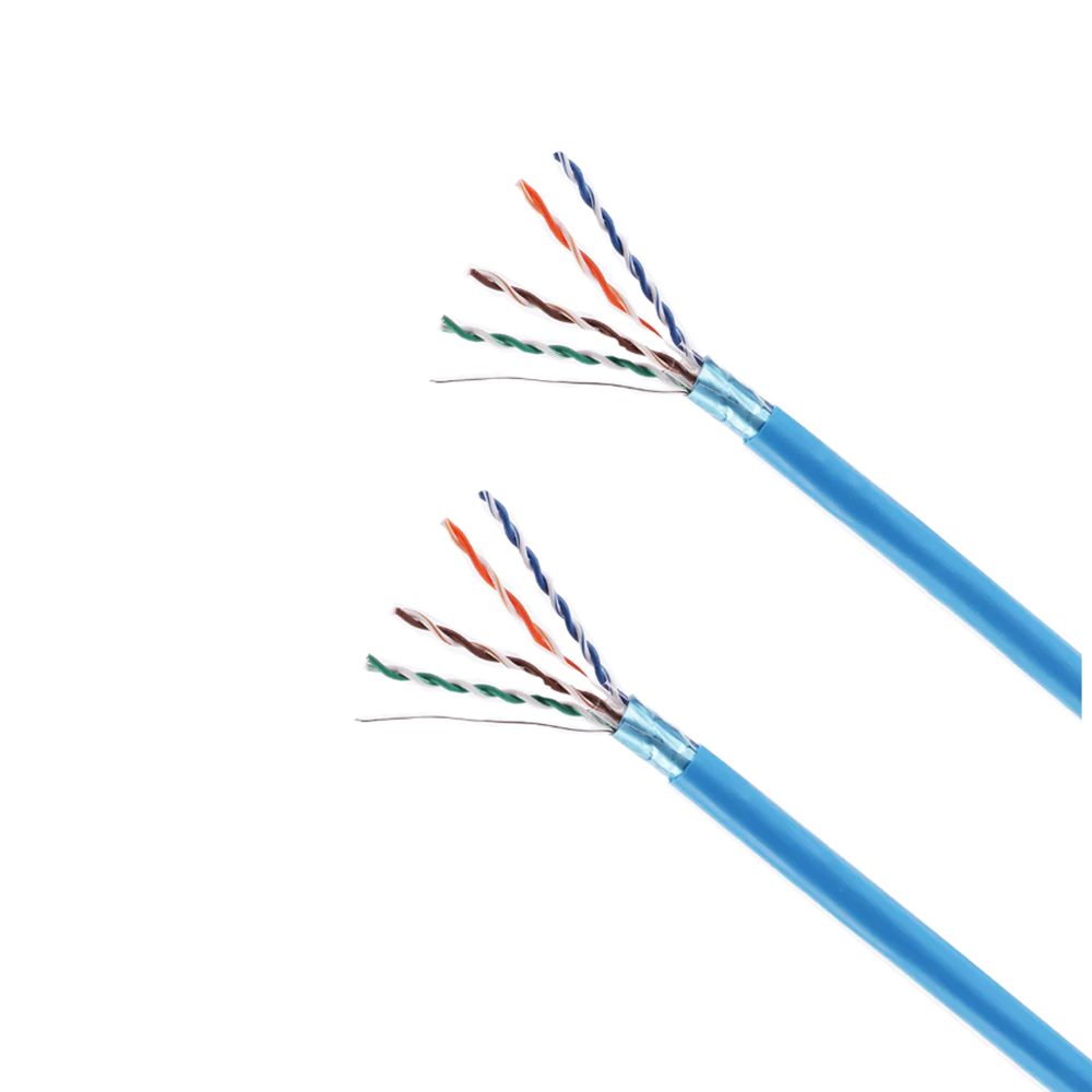 Cat6 Shielded Industrial Ethernet CableFor noisy plant-floor Ethernet runs, this shielded Cat6 cable supports Gigabit and short-distance 10 Gigabit with strong EMI protection.View Product →
For plant-floor Ethernet, a Cat6 construction with solid dielectric and consistent pair geometry holds its 100 Ω target across the run and tolerates the electrical noise that comes with drives and contactors nearby.
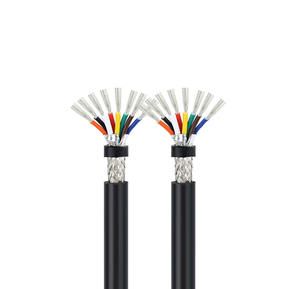
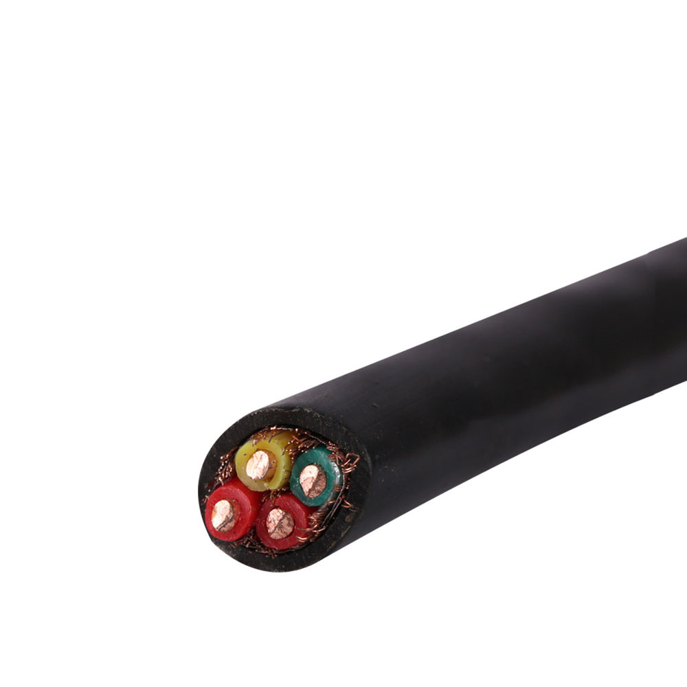 KVVP Shielded PVC Control CableFor switching signals between cabinets, this copper-braided shielded control cable suppresses electromagnetic interference and suits fixed indoor installations.View Product →
Where a shielded control cable carries switching signals between cabinets, the braided screen does double duty: it keeps the field contained and keeps external interference from distorting the signal the controller is trying to read.
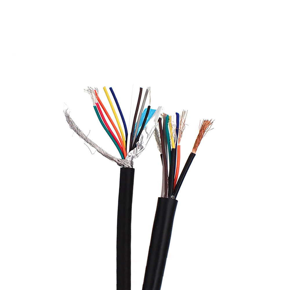
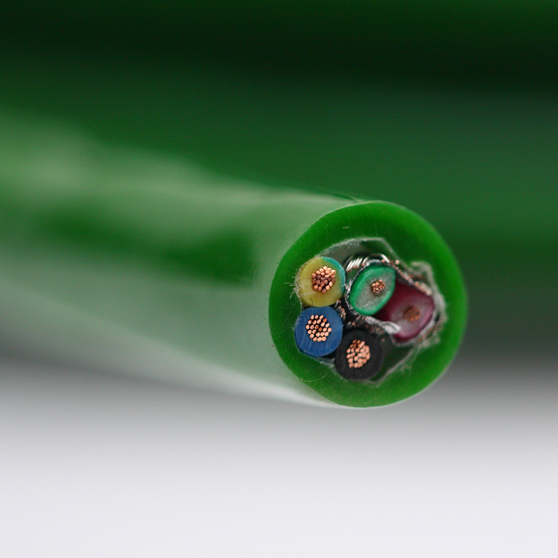 High Anti-Interference Computer Encoder CableFor encoder feedback on fast motion axes, multi-layer shielding and stable impedance help protect weak differential signals from motor and inverter noise.View Product →
Encoder and motion feedback lines are the classic case where impedance and shielding have to be right together, because a single reflection on a fast pulse train turns into a position error rather than a slightly softer waveform.
If the cable sits inside a wider automation or robotics build, it often makes sense to look at the whole harness at once rather than one part number at a time — our automation cable solutions page shows how power, control, and feedback cables are usually combined.
Impedance is one of those subjects where a five-minute conversation saves a fortnight of rework. If you are unsure whether your application needs a 100 Ω or a 120 Ω construction, or whether the run length is even long enough for impedance to matter, tell us the equipment, the environment, and the distance. We will tell you honestly if a standard product will do the job, and if it will not, we will explain which part of the construction needs to change and why.
That approach comes from being a manufacturer rather than a catalogue: the people answering the question are the same people who set the extrusion and lay-length parameters on the line.

We firmly believe that good cables are not only a competition of materials, but also a reflection of craftsmanship, quality, and responsibility.

Links
Product
Send Inquiry
No. 29 Sankeshu Road, Xuanzhou District, Xuancheng City, Anhui Province, China
+86-18621104555/+86-563-2622999
 Electrical Cable Manufacturer
OEM/ODM Wire and Cable Solutions
 English
 Español
 عربى
 русский