
Get more content that can help you
Content
In modern computing environments — from high-frequency trading servers and AI training clusters to professional workstations and 8K video editing rigs — the cable is rarely the first component engineers think about. Yet transmission stability is the foundational requirement that determines whether high-performance hardware actually delivers its rated throughput in real-world conditions. A cable that introduces signal degradation, electromagnetic interference, or impedance discontinuities will throttle data rates, increase error correction overhead, and in severe cases cause system hangs, corrupted data, or dropped connections. Understanding what governs transmission stability in high-performance computer cables is therefore essential knowledge for anyone designing, building, or maintaining a system where data integrity and speed both matter.
Transmission stability is not a single property — it is the combined outcome of conductor geometry, insulation dielectric characteristics, shielding architecture, connector termination quality, and cable assembly precision. Each of these elements contributes independently to the overall signal chain, and weakness in any one area can dominate the performance of an otherwise well-specified cable assembly.
The conductor is where electrical signals travel, and its physical characteristics directly determine how faithfully a high-frequency signal is transmitted from one end of the cable to the other. At high data rates — USB 4, Thunderbolt 4, PCIe Gen 4/5, or 100GbE — the skin effect becomes significant: current concentrates increasingly at the outer surface of the conductor as frequency rises, effectively reducing the usable cross-sectional area and increasing resistance. This elevates insertion loss and attenuates high-frequency signal components, causing waveform distortion at the receiver.
High-performance cables address this through several conductor strategies. Silver-plated copper conductors are common in premium data cables because silver's marginally higher surface conductivity reduces skin-effect losses compared to bare copper. Solid conductors are preferred over stranded for fixed installations because stranding introduces small but measurable impedance variations at each wire contact point. For flexible applications where stranded conductors are necessary, tightly controlled strand geometry and lay length minimize this effect. The conductor diameter must also be precisely matched to the cable's characteristic impedance target — typically 50Ω for coaxial RF cables or 100Ω differential for high-speed data pairs.
The insulation surrounding each conductor — the dielectric — is not electrically inert. Every dielectric material has a characteristic permittivity (dielectric constant) that directly affects the propagation velocity of signals through the cable and the cable's characteristic impedance. Variations in dielectric constant along the cable length translate directly into impedance discontinuities, which cause signal reflections. In high-speed digital systems, these reflections appear as noise on the signal eye diagram and increase bit error rates.
Standard PVC insulation, adequate for low-frequency applications, has a relatively high and variable dielectric constant that makes it poorly suited for high-speed data cables. High-performance computer cables instead use low-loss dielectric materials that maintain consistent properties across the frequency ranges of interest.
Manufacturing consistency of the dielectric wall thickness is equally important. Eccentricity — where the conductor is off-center within the insulation — creates periodic impedance variations that generate return loss and worsen signal integrity. High-performance cable manufacturers use precision extrusion equipment with real-time wall thickness monitoring to minimize eccentricity to fractions of a millimeter.
Electromagnetic interference (EMI) — both from external sources coupling into the cable and from signals within the cable radiating outward — is one of the most practical threats to transmission stability in real-world computing environments. Server rooms, data centers, and industrial computing installations are electrically noisy places, filled with switching power supplies, cooling fans, wireless radios, and high-current motor drives. A cable without adequate shielding will pick up this noise on the signal conductors, degrading the signal-to-noise ratio and increasing errors.
High-performance computer cables use layered shielding strategies to provide both high coverage and broad-frequency effectiveness. The performance of a shielding system is quantified by its transfer impedance and shield coverage percentage — lower transfer impedance and higher coverage both indicate better EMI rejection.
| Shield Type | Coverage | Best Frequency Range | Typical Application |
| Aluminum foil (AL/PET) | 100% | Mid to high frequency | Cat 6A, STP data cables |
| Tinned copper braid | 85–98% | Low to mid frequency | USB, HDMI, coaxial |
| Foil + braid (double shield) | >98% | Broadband | Thunderbolt, 10GbE, premium AV |
| Spiral serve shield | 90–95% | Low frequency, flexible use | Flexible robotic and drag-chain cables |
For differential signal pairs — the architecture used in USB, Thunderbolt, DisplayPort, and Ethernet — individual pair shielding (S/FTP or U/FTP construction) provides the highest crosstalk rejection between pairs within the same cable. This is critical when multiple high-speed pairs share a cable jacket, as in Cat 8 Ethernet or active optical cable assemblies.
Modern high-speed computer interfaces — including USB 3.2, PCIe, DisplayPort 2.1, and all variants of Ethernet above 1GbE — use differential signaling, where data is transmitted as the voltage difference between two conductors carrying complementary signals. This technique provides inherent immunity to common-mode noise, but it depends critically on the physical symmetry of the two conductors within each pair. Any geometric asymmetry — different insulation thickness, unequal lay length, or inconsistent spacing — causes the pair to become skewed, where one conductor's signal arrives at the receiver slightly before the other. At multi-gigabit data rates, even picoseconds of skew can cause receiver decoding errors.
The twist rate of differential pairs is carefully engineered to balance two competing requirements: tight, consistent twisting improves common-mode rejection and mechanical symmetry, but excessively tight twisting increases the cable's length relative to its route (affecting skew between pairs) and can introduce stress into the conductors. Different pairs within a multi-pair cable are deliberately given slightly different twist rates so that each pair has a unique electrical length, preventing resonant crosstalk coupling between pairs at specific frequencies.
A cable assembly's transmission stability is only as good as its weakest connection point, and connectors are consistently the most failure-prone element of any cable assembly. At the connector interface, mechanical precision, contact material, and termination method all directly influence signal integrity. Impedance discontinuities at connectors are inevitable — the geometry changes abruptly at the transition from cable to connector — but high-performance connector designs minimize the electrical length of this discontinuity and use matched impedance structures to reduce reflections.
Gold-plated contacts are the standard for high-reliability computer cable connectors because gold's resistance to oxidation maintains low, stable contact resistance over thousands of mating cycles and years of service. Contact resistance that rises over time — due to oxidation on base metal contacts — increases insertion loss and introduces signal reflections. For high-speed applications, the connector's return loss specification (a measure of how well the connector maintains impedance matching) should be verified against the protocol's requirements. USB4 and Thunderbolt 4 cables, for instance, carry connector performance specifications as demanding as the cable itself.
Passive cable assemblies — those containing only conductors, insulation, shielding, and connectors — are subject to fundamental physical limits on the length over which they can maintain adequate signal quality. As cable length increases, insertion loss accumulates and the received signal amplitude diminishes. Every protocol defines a maximum insertion loss budget that the cable plus connectors must stay within. Exceeding this budget causes the receiver's equalizer to fail to compensate, resulting in bit errors.
For applications requiring lengths beyond the passive cable limit, active cables incorporate signal conditioning electronics — typically retimers or redrivers — within the cable assembly itself. Active optical cables (AOCs) convert the electrical signal to optical at one end and back to electrical at the other, virtually eliminating length-related insertion loss for runs of tens of meters. These active approaches maintain transmission stability over distances that would be physically impossible with passive copper alone, making them essential for data center interconnects, storage area networks, and high-performance computing cluster backplane connections.
Specifying a high-performance cable is only the beginning — verifying that it actually delivers stable transmission in the target installation is equally important. The key electrical parameters that should be tested or confirmed against datasheets include insertion loss (attenuation), return loss, near-end crosstalk (NEXT), far-end crosstalk (FEXT), propagation delay, and skew between pairs. For structured cabling installations, field testers such as the Fluke DSX series can measure all these parameters and certify that the installed cable plant meets its rated category.
For individual cable assemblies — a Thunderbolt 4 cable, a high-speed HDMI assembly, or a PCIe Gen 5 riser — protocol-specific compliance testing performed by the relevant industry certification body provides the strongest assurance of transmission stability across the full range of operating conditions. Purchasing certified assemblies from reputable manufacturers, rather than unbranded alternatives that claim compliance without testing evidence, is the most reliable way to ensure that transmission stability meets the demands of high-performance computing applications over the long term.


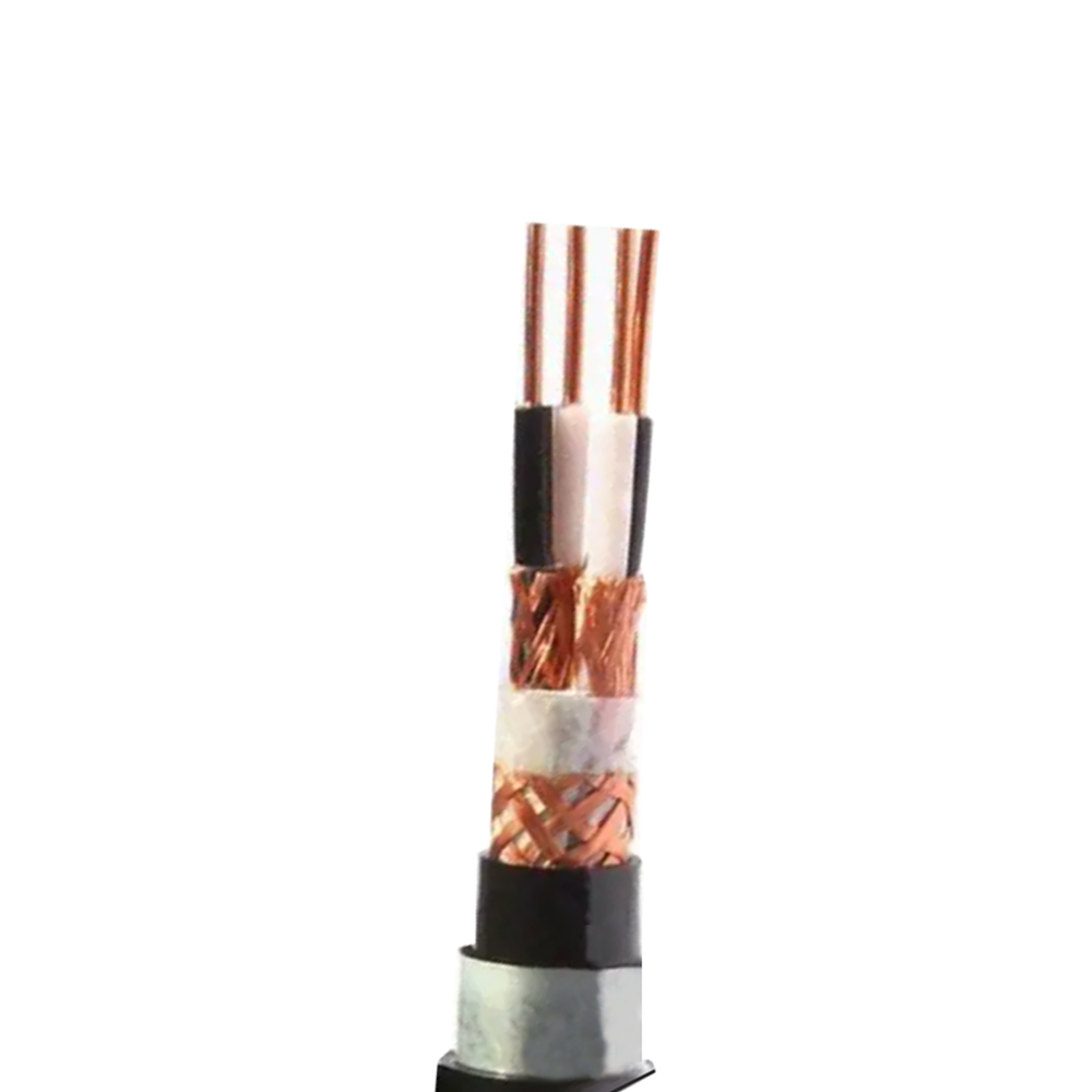
-YJY23 XLPE Insulated and Sheathed Power Cable")
We firmly believe that good cables are not only a competition of materials, but also a reflection of craftsmanship, quality, and responsibility.

Links
Product
Send Inquiry
No. 29 Sankeshu Road, Xuanzhou District, Xuancheng City, Anhui Province, China
+86-18621104555/+86-563-2622999
 English
 Español
 عربى
عربى
 русский