

Get more content that can help you
Content
Ask a data center operations team what keeps them awake at night and servers rarely top the list. The cables that feed those servers, the terminations behind them, and the derating calculations nobody enjoys re-checking cause far more unplanned downtime than most people outside the industry realize. In engineering terms, a data center is an industrial power distribution system that happens to share a building with a great deal of IT equipment. Every kilowatt drawn by a rack travels through a chain of conductors that begins at the utility service and ends at a rack PDU.
After years of manufacturing cable for industrial, energy, and infrastructure projects, we have watched small specification decisions ripple through commissioning schedules and maintenance budgets. This guide covers what genuinely matters when you select, install, and maintain data center power cables.
A cable installed in an office building and a cable installed in a data hall may look similar on the outside, but they live very different lives. Several operating realities separate the two:
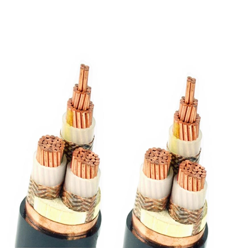
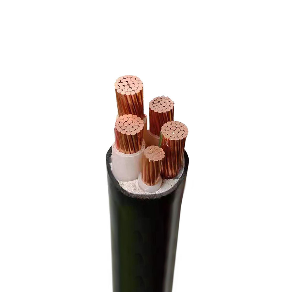
Before comparing supplier data sheets, it helps to know which layer of the cable performs which job. A typical medium-voltage or low-voltage power cable used in a data environment is built from the following elements:
Data center power distribution is a chain, and each stage has its own electrical and environmental pressures. The table below summarizes how the requirements shift from the utility entrance down to the white space.
| Power stage | Typical voltage | Common insulation | Primary priority |
|---|---|---|---|
| Utility service entrance | 10 to 35 kV | XLPE | Dielectric strength, moisture protection |
| Transformer to main switchboard | 400 to 690 V | XLPE or PVC | Ampacity, short-circuit withstand |
| UPS input and output | 400 V | XLPE, low smoke | Harmonic tolerance, fire performance |
| PDU and busway feeds | 400 V | XLPE | Compact bending radius, tray fill |
| Rack-level circuits | 230 to 400 V | Low smoke halogen-free | Flexibility, airflow-friendly routing |
| Control and monitoring | 24 to 300 V | PE or PVC with shield | Electromagnetic compatibility, signal stability |
Most of the cable volume in a data hall sits on the low-voltage side, where feeders run from switchboards and UPS output breakers to PDUs and busway taps. These runs are long, densely grouped, and rarely accessible once the floor is live, which makes material selection a decision you live with for years. Standard low-voltage XLPE power cable remains an excellent baseline for this duty. Where the environment combines humidity, chemical exposure, or wash-down cleaning with strict fire requirements, halogen-free variants with a mica barrier are worth the modest cost premium.
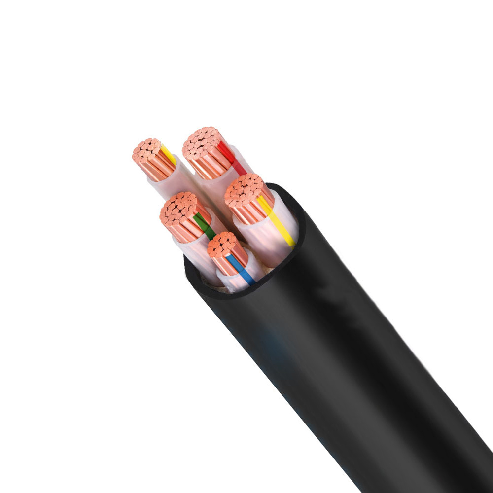 YJV Heat resistance XLPE Insulated and Sheathed Power CableExcellent heat resistance: Long-term operating temperature of 90°C, with overload capacity far superior to ordinary PVC cables (VV cables). High current-carrying capac...View Product →
UPS rooms, battery rooms, and fuel-cell or battery energy storage installations bring their own cable challenges: DC runs with high continuous current, elevated ambient temperatures, and tight clearances around equipment. Grouping and ambient correction factors matter enormously here, and flexible conductors simplify the awkward bends around battery racks and inverter terminals. Teams planning a storage upgrade alongside a power train refresh can review our energy storage project solutions for layout and material guidance before the design is frozen.
Ampacity tables are a starting point, not an answer. Real installations stack correction factors until the usable capacity of a cable is noticeably lower than the catalogue figure. Ambient temperature in a hot aisle or a rooftop plant room, grouping of parallel runs, tray fill, thermal insulation, and burial depth all reduce the permissible current. Harmonic content adds another layer, because distorted current raises the root-mean-square value and increases skin effect losses in the conductor. On the neutral side, triplen harmonics can sum rather than cancel, so a neutral sized at the phase conductor's rating may run hotter than expected. The practical answer is to size generously, to document every correction factor applied, and to leave margin for future rack density increases.
Even a perfectly specified cable can fail early if the installation ignores basic physics. Keep power and data pathways physically separated, or use shielded constructions where they must cross. Respect the minimum bend radius stated by the manufacturer, because a single over-tight bend during a pull can permanently damage insulation. Support cables at recommended intervals to avoid mechanical stress at terminations, and never pull cable through a bend that a person cannot walk through comfortably. Where feeders leave the building through duct banks or buried routes, armored constructions with a robust oversheath handle soil movement, moisture, and rodent activity far better than an unarmored equivalent.
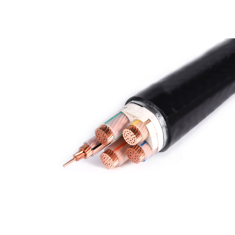 YJV22 Mechanical protection XLPE Insulated and Sheathed Power CableExcellent mechanical protection (core advantage): Steel tape armor provides extremely high radial compression and impact resistance, enabling direct burial underground...View Product →
Terminations and joints deserve the same care as the cable itself. Contamination during preparation, incorrect torque, and mismatched lug materials are among the most common causes of hot spots found during infrared surveys.
Fire performance in a data center is usually described by three test families: flame propagation along a vertically mounted tray, acid gas emission during combustion, and smoke density. Low-smoke zero-halogen sheathing addresses the last two, which matters when a facility must protect both occupants and sensitive electronics during an incident. For circuits that must keep working while a fire is being fought, circuit-integrity constructions with a mineral or mica barrier are the standard answer, and they are frequently specified for emergency lighting, fire pumps, exhaust fans, and critical control circuits.
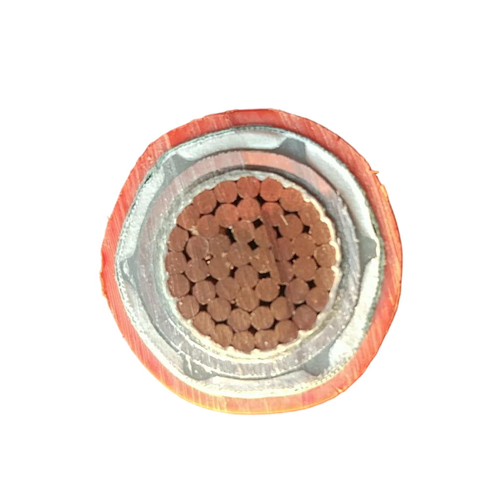 BTLY Waterproof and moisture-proof Flexible Mineral-Insulated Fire-Resistant CableExcellent Fire Resistance and Fire Safety (Core Advantage): True "fire-resistant cable": Not only can it maintain power supply during a fire (fire resistance), but it ...View Product →
Beyond cable construction, inspectors will look for compliance with the governing electrical code, local fire regulations, and any certification scheme the project agreed to, whether that means CE marking, UL listing, or an equivalent national approval. Documenting test reports up front prevents awkward conversations during sign-off.
Rack densities keep climbing, and a cable system designed for ten kilowatts per rack can quickly become a bottleneck at thirty. Several design choices ease that transition: favor busway or plug-in systems in the white space so capacity can be added without new pulls, keep spare conduits and tray capacity in the base build, and choose flexible conductors for final connections where equipment is expected to move. Direct-current distribution at higher voltages is also gaining ground in efficiency-focused designs, and it places fresh demands on insulation thickness and clearance that are best addressed early in the layout phase.
Once the drawings are close to final, run through the following points with your cable supplier before releasing a purchase order:
Data center power cables sit at the intersection of electrical performance, fire safety, and mechanical durability, and the specification rarely gets simpler over time. Working with a manufacturer who can discuss conductor stranding, insulation compounds, shielding options, and certification routes in the same conversation saves weeks of back-and-forth during design. Our engineering and quality teams support projects from first sizing calculations through factory testing and delivery, and we are always glad to review a cable schedule against the realities of the installation environment. A short conversation early usually prevents an expensive change order later.
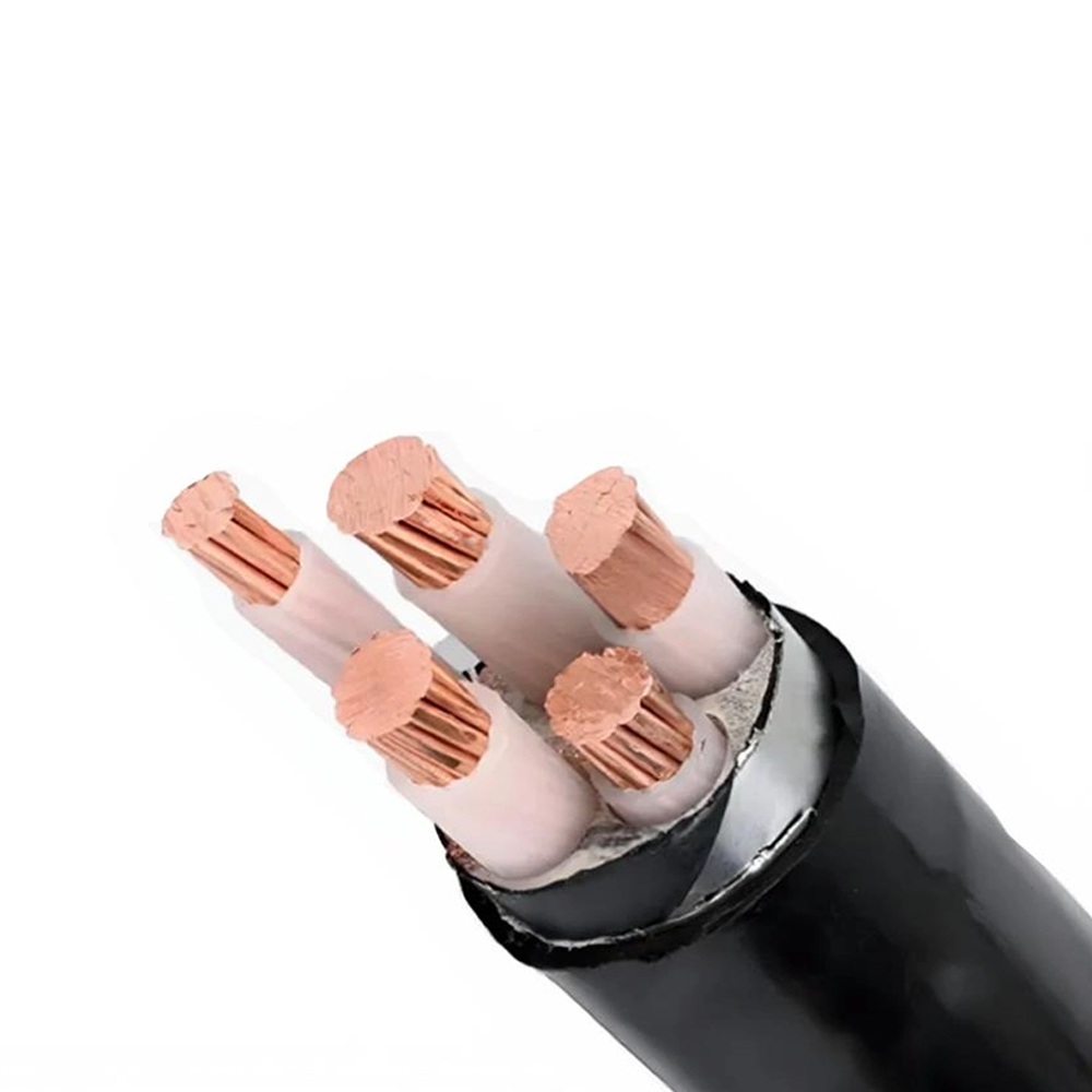


We firmly believe that good cables are not only a competition of materials, but also a reflection of craftsmanship, quality, and responsibility.

Links
Product
Send Inquiry
No. 29 Sankeshu Road, Xuanzhou District, Xuancheng City, Anhui Province, China
+86-18621104555/+86-563-2622999
 Electrical Cable Manufacturer
OEM/ODM Wire and Cable Solutions
Electrical Cable Manufacturer
OEM/ODM Wire and Cable Solutions
 English
 Español
 عربى
عربى
 русский