

Get more content that can help you
Content
Utilities and grid contractors upgrading distribution networks increasingly move away from bare conductor lines in favor of aerial insulated cable systems. This shift is driven by safety concerns, environmental adaptability, and long-term cost considerations that bare conductors struggle to address in dense or environmentally challenging areas. This article examines how medium and low-voltage aerial insulated cables are built, what types suit different installation scenarios, and what production factors determine long-term field performance.
Aerial insulated cables retain the practical advantages of overhead installation, such as using existing pole infrastructure and avoiding the excavation costs of underground cabling, while wrapping the conductor in a dedicated insulation layer. This single design change addresses several of the most persistent problems associated with bare overhead lines, including accidental contact risk, short circuits caused by tree branches or debris, and phase-to-phase clearance requirements that consume corridor space. Because the conductor is fully insulated, phase spacing can be reduced substantially compared to bare conductor lines, allowing utilities to run more capacity through the same physical corridor width.
Several structural characteristics distinguish a well-engineered aerial insulated cable from a basic insulated wire, and each addresses a specific field condition the cable will face over its service life.
The conductor is completely enclosed within an insulation layer, removing the direct shock hazard that bare conductors present to people, animals, and equipment that may come into incidental contact with the line during storms, tree contact, or maintenance work nearby.
Insulation compounds are formulated to resist degradation from prolonged ultraviolet exposure, ozone, and repeated temperature cycling. Without this resistance, insulation would crack or embrittle over time, eventually exposing the conductor and defeating the purpose of the insulated design.
Overhead cables must support their own weight across spans while also withstanding wind loading and, in colder climates, ice accumulation. Reinforcing elements, whether integrated steel cores or separate load-bearing strands, are engineered into the cable structure to carry this mechanical load without placing excess strain on the conductor or insulation itself.
Aerial insulated cables are produced in several configurations, each suited to specific voltage levels, span requirements, or environmental conditions. Selecting the correct type is central to achieving reliable long-term performance.
| Cable Type | Typical Application |
| Low-voltage aerial cable (0.6/1kV) | Urban residential distribution and rural grid upgrades |
| Medium-voltage aerial cable (10kV/35kV) | Urban-rural fringe areas and industrial park supply |
| Self-supporting aerial cable | Long-span installations requiring simplified support structures |
| Bundled aerial cable | Narrow streets and space-constrained corridors |
| Waterproof aerial cable | Coastal and high-rainfall regions |
| Weather-resistant aerial cable | High-altitude and high-UV exposure areas |
| Fire-resistant aerial cable | Forested regions and other fire-sensitive environments |
The field performance of an aerial insulated cable is set largely during manufacturing, where several process controls directly affect service life and mechanical behavior once installed.
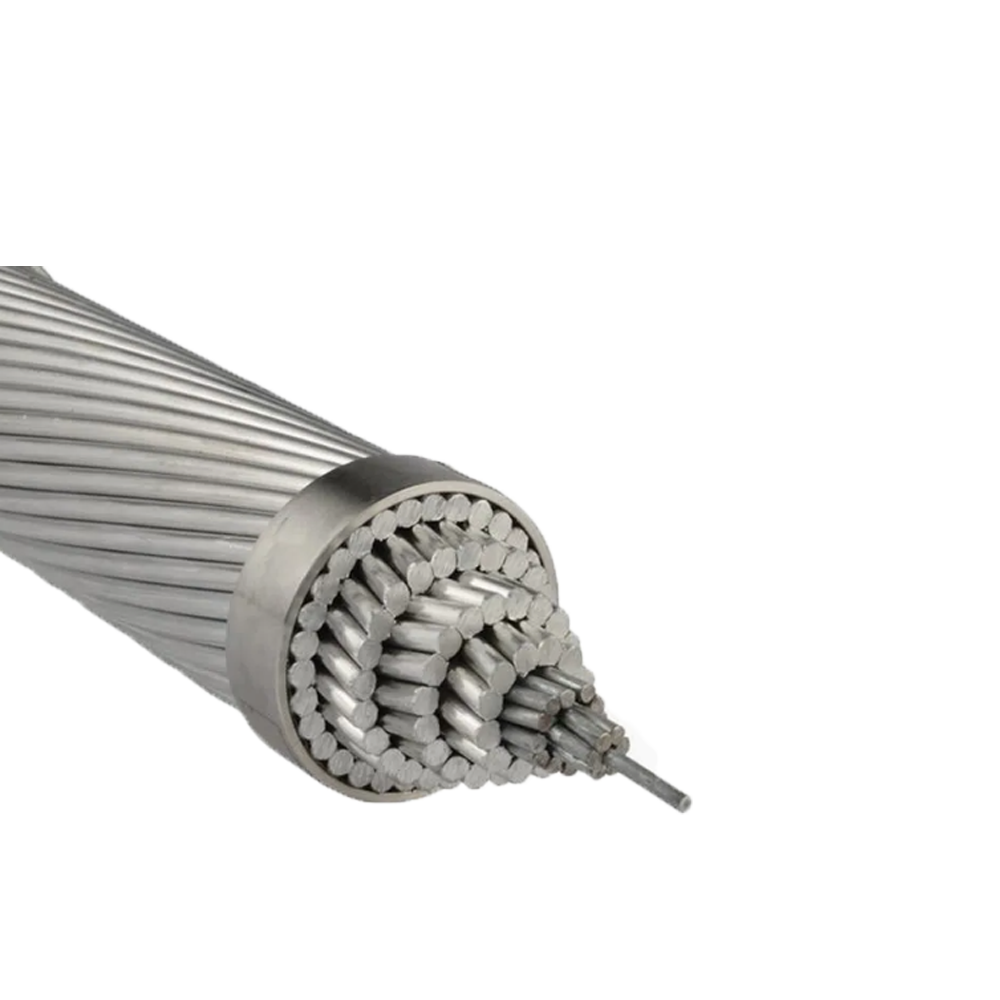
Conductors are typically manufactured from hard aluminum or aluminum alloy to balance conductivity with the mechanical strength needed for overhead spans. Compacting the conductor strands reduces the overall outer diameter and produces a smoother surface, which improves the quality of the bond with the surrounding insulation layer.
Insulation is applied using weather-resistant polyethylene, cross-linked polyethylene, or specialized composite compounds, with UV inhibitors such as carbon black incorporated at carefully controlled concentrations, generally in the range of 2.5 to 3.0 percent, to provide long-term protection against sunlight-driven degradation without compromising the insulation's electrical properties.
Higher-quality cables use a triple-layer co-extrusion process that applies the conductor shielding, main insulation, and insulation shielding simultaneously. This approach produces smoother, more defect-free interfaces between layers than sequential extrusion, reducing the risk of localized electrical stress points that could shorten insulation life.
Steel cores or high-strength non-metallic reinforcements are concentrically twisted with the insulated cores to distribute mechanical tension evenly across the cable structure. Outer sheaths are formulated for tear resistance and environmental stress crack resistance, with wall thickness controlled within roughly plus or minus 10 percent to maintain consistent mechanical and electrical performance along the full cable length.
The practical case for aerial insulated cable adoption rests on several measurable advantages over traditional bare conductor lines.
While aerial insulated cables can be applied broadly across distribution networks, certain contexts see particularly strong returns on the upgrade. Urban distribution networks benefit from the safety improvement in densely populated corridors where bare conductors pose ongoing contact risk. Rural grid upgrades gain from reduced tree-trimming requirements, since insulated lines tolerate incidental branch contact that would otherwise cause outages on bare lines. Coastal installations benefit from waterproof cable variants engineered to resist salt spray corrosion, extending line life in an environment that accelerates degradation of unprotected hardware. Mountainous and complex-terrain transmission routes benefit from the reduced clearance requirements and installation flexibility that insulated cable systems provide, allowing lines to be routed through tighter corridors than bare conductor standards would permit.
Selecting the right aerial insulated cable configuration for a given project requires balancing several factors together rather than optimizing for any single criterion. Voltage class determines the base cable family, while span length and terrain influence whether a self-supporting design is needed. Local climate conditions, including UV exposure, coastal salt spray, or fire risk, point toward specialized variants engineered for those specific stresses. Budget and installation timeline also factor into the decision, since compatibility with existing pole infrastructure generally keeps both material and labor costs lower than alternative undergrounding approaches. Evaluating these factors together against a project's specific site conditions helps ensure the selected cable delivers the reliability and service life the installation is designed for.
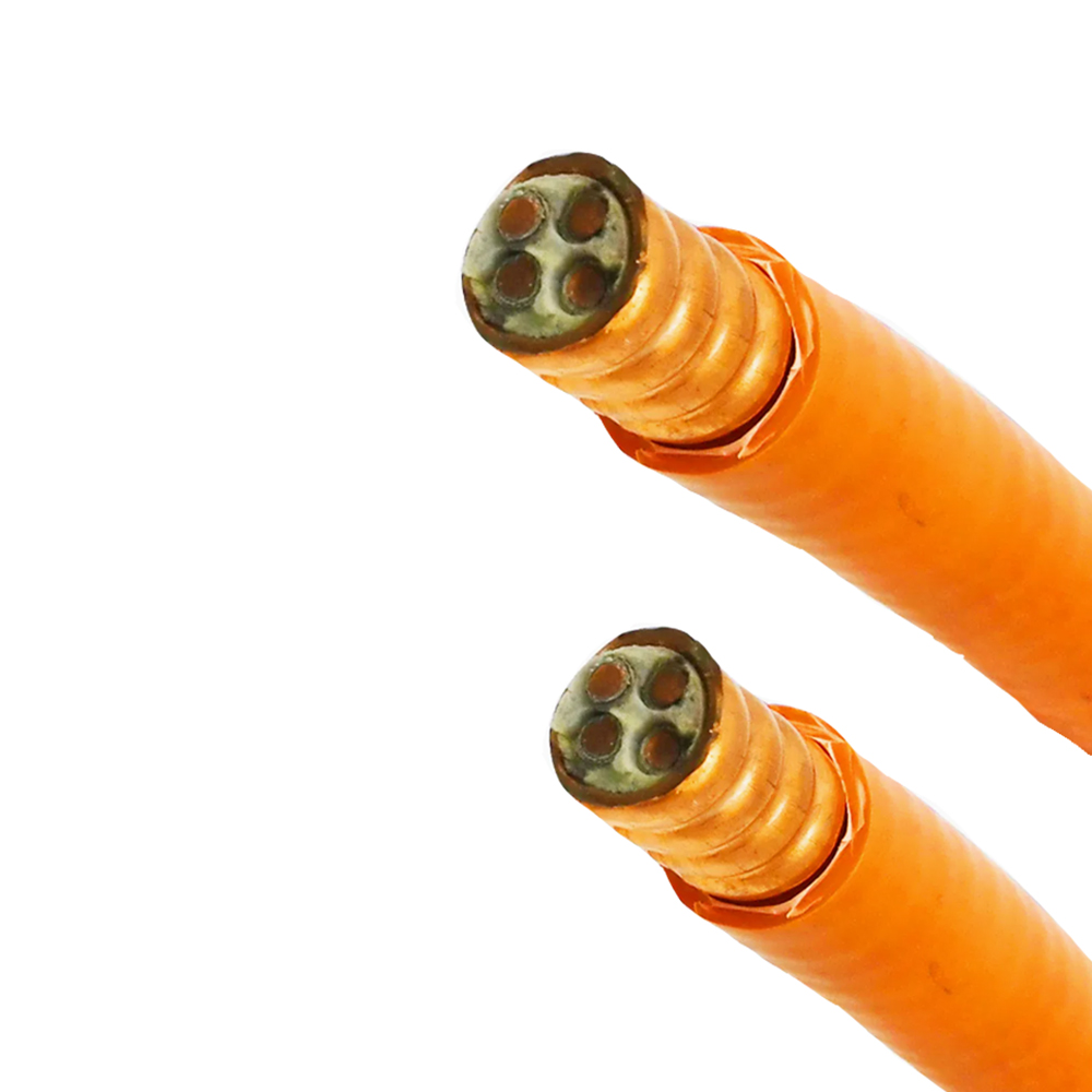
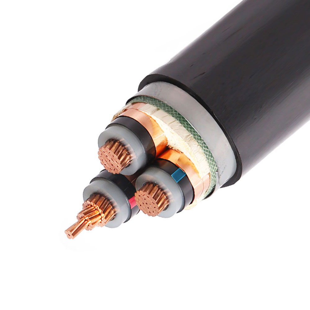
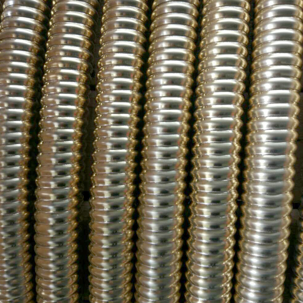
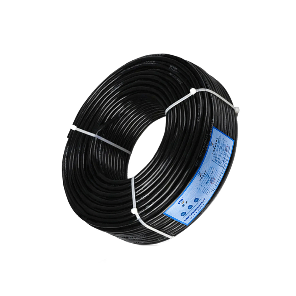
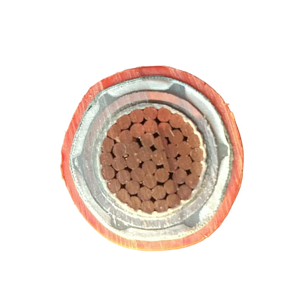

We firmly believe that good cables are not only a competition of materials, but also a reflection of craftsmanship, quality, and responsibility.

Links
Product
Send Inquiry
No. 29 Sankeshu Road, Xuanzhou District, Xuancheng City, Anhui Province, China
+86-18621104555/+86-563-2622999
 Electrical Cable Manufacturer
OEM/ODM Wire and Cable Solutions
Electrical Cable Manufacturer
OEM/ODM Wire and Cable Solutions
 English
 Español
 عربى
عربى
 русский