

Get more content that can help you
Content
At a 110 kV substation, an engineer sees a feeder relay trip twice in one month. Both times the fault disappears before crews arrive. The utility installs line-mounted current and temperature sensors. The data set identifies a loose connector that only fails during peak load. That was not an expensive discovery, but it depended on a whole chain of components, from the sensor itself to the cable that carries the signal back to the substation.
Power grid sensors technology is no longer an optional add-on for utilities or industrial power users. It is the foundation for fault localization, predictive maintenance, and dynamic load management. But the technology only delivers value when the complete measurement chain works, and that chain includes the cable.
The primary drivers are straightforward. Utilities face aging assets, tighter budgets, and rising expectations for grid reliability. Instead of dispatching a crew to patrol every kilometer of a feeder, they can install a small number of sensors that continuously measure current, temperature, vibration, or partial discharge. The data reveals anomalies that are invisible to a visual inspection.
When the measurement chain works reliably, the result is a shorter time to restore service, better asset utilization, and fewer unnecessary maintenance visits. The investment is usually justified by a single avoided outage.
Grid sensor deployments split into a few repeatable use cases. Understanding each one helps clarify the specification priorities:
Every one of these use cases ends with a signal that must reach a data logger, RTU, or gateway. That signal path is where a poorly selected cable can ruin the entire sensor investment. A shield with insufficient coverage, a jacket material that withstands the wrong environmental stress, or an impedance mismatch can turn a high-accuracy measurement into misleading data.
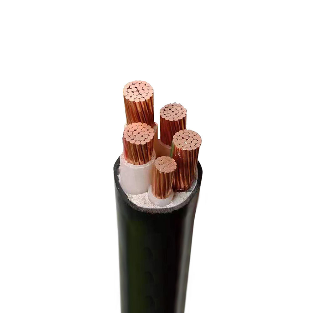
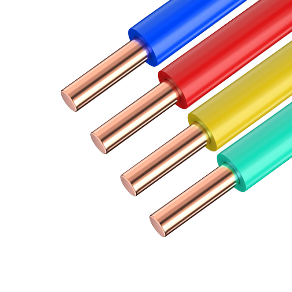 Sensor Signal Cables for Accurate Low-Level Signal TransmissionThese precision cables are designed to carry millivolt or milliampere signals from sensors to control systems. Their shielding and low capacitance ensure signal integrity in substation environments with electromagnetic interference.View Product →
For this reason, utilities and system integrators increasingly specify dedicated sensor signal cables, designed with low capacitance and good electromagnetic interference rejection. These cables are not ordinary building wires. They are built for continuous signal fidelity in the presence of switchgear transients and 50/60 Hz fields.
The sensor market is broad, and different technologies return different quality of information. The table below gives a practical overview of the most common types used in grid monitoring.
| Sensor Type | What It Measures | Typical Grid Application | Critical Specification |
|---|---|---|---|
| Current transformer (CT) | Current magnitude | Feeder load monitoring, fault detection | Accuracy class and burden rating |
| Voltage sensor | Voltage level | Substation bus voltage, power quality studies | Insulation level and scaling accuracy |
| Temperature sensor | Conductor temperature | Dynamic line rating, connector hot spot detection | Accuracy class and response time constant |
| Partial discharge sensor | Insulation activity | Underground cable and transformer condition | Sensitivity and noise rejection |
| Vibration sensor | Mechanical movement | Transformer and switchgear condition monitoring | Frequency range and mounting |
The last column is where engineering teams often disagree. A temperature sensor can be accurate to 0.5 °C, but if its lead wire is exposed to high electromagnetic interference, the value recorded at the data logger can be far from the real conductor temperature. The installation environment therefore makes the sensor specification directly dependent on the cable specification.
Sensors are installed in many different physical environments. Some sit on live conductors on a transmission tower. Others sit inside a switchgear cubicle near power transformers. A third group is buried in manholes along an underground distribution route. Each environment drives a different cable requirement.
For outdoor pole-mounted sensors, the signal cable must withstand UV radiation, rain, and large temperature swings. For substation installations, the cable needs to tolerate strong magnetic fields and transient voltage spikes. For underground applications, moisture resistance and rodent protection become more significant than signal accuracy itself.
Where sensors need to communicate over long distances on a high-voltage network, a fiber optic composite cable can combine power conductors with communication fibers in a single sheath. This design reduces the need for separate communication infrastructure and often improves reliability in exposed substation environments.
Fiber Optic Composite Cables Combining Power and CommunicationHybrid cables integrate optical fibers with power conductors in a single sheath, reducing installation complexity and improving reliability for long-distance sensor communication on high-voltage networks.View Product →
It also creates a practical advantage for project teams. Instead of coordinating a separate fiber pull and a power cable pull with two different installation crews, the composite construction allows a single cable to be trenched or strung. That saves labor and eliminates one element of schedule risk.
Procurement decisions for grid monitoring systems often focus on sensor cost and brand. The cable, however, is frequently left as a default item and replaced later during commissioning troubleshooting.
A practical way to avoid that is to check three parameters before ordering:
Control cables often serve as the interface between sensor junction boxes and the remote terminal unit (RTU) in a substation. A flame-retardant control cable with low smoke and halogen-free properties reduces fire risk while providing the mechanical protection needed in harsh locations.
Halogen-Free Low Smoke Control Cables for Substation ConnectionsFlame-retardant control cables with low smoke and halogen-free properties provide mechanical protection and reduce fire risk as the interface between sensor junction boxes and remote terminal units.View Product →
For teams using IEC 61850 or similar communication architectures, the cable must also support the required bandwidth and distance. Selecting a cable with a larger conductor size than strictly necessary can simplify future upgrades without adding much cost to the overall sensor project.
The next stage of industry practice will likely combine distributed sensors with analytics rather than adding more standalone monitoring equipment. Dynamic line rating algorithms already use weather data and conductor temperature sensors to guide dispatch decisions. Partial discharge data is being integrated with asset management databases to prioritize cable replacement over reactive repair.
Drones and thermal cameras are increasing the coverage of overhead line inspections, but they provide snapshots, not continuous data. Permanent sensors and periodic drone surveys are increasingly viewed as complementary tools. The sensor sets the baseline, and the drone picks up outliers.
For a cable manufacturer, the most relevant shift is toward longer sensor chains and more complex communication paths. Power companies are asking for simple, robust products that survive the installation environment. That is where automation solutions help define which cables and electrical components belong together. In harsh industrial zones, the same principle applies, and guidance on ensuring safety with instrumentation cables offers a useful reference for engineers working on sensor retrofits.
Deployed correctly, power grid sensors technology turns a reactive maintenance model into a preventive one. The payoff is measured not only in avoided outages but also in better asset utilization and safer field operations. From the sensor head to the termination in the control room, every connection matters.

We firmly believe that good cables are not only a competition of materials, but also a reflection of craftsmanship, quality, and responsibility.

Links
Product
Send Inquiry
No. 29 Sankeshu Road, Xuanzhou District, Xuancheng City, Anhui Province, China
+86-18621104555/+86-563-2622999
 Electrical Cable Manufacturer
OEM/ODM Wire and Cable Solutions
Electrical Cable Manufacturer
OEM/ODM Wire and Cable Solutions
 English
 Español
 عربى
عربى
 русский