
Get more content that can help you
Content
If you hold the cut end of a live fiber-optic patch cord up to a wall and see a faint red glow, you are looking at the signal itself. That glow is data: a tiny light source switching on and off millions of times per second. An optical cable works by converting electrical signals into pulses of light, guiding those pulses through a hair-thin strand of glass or plastic, and converting them back into electrical signals at the far end. Because the information travels as photons rather than electrons, it can cross tens or even hundreds of kilometers with low loss, high bandwidth, and complete immunity to electromagnetic interference. One caution before anything else: never look directly into the end of a connected fiber, since the invisible infrared light used in real networks can permanently injure your eyes. The sections below explain the physics step by step, then connect each principle to the details that matter when you specify, buy, or install cable for a real project.
Conclusion first: an optical cable is a precision light pipe wrapped in protection. Its working part is a strand of ultra-pure glass drawn thinner than a human hair; everything else exists to keep light inside that strand and keep the strand itself intact.
The glass is so pure that engineers like to say the ocean, if made of it, would let you see the seabed from the surface. Light can travel many kilometers before even half of it is lost.
The guiding principle is total internal reflection. The core is doped to have a higher refractive index than the cladding, roughly 1.48 versus 1.44 in typical multimode fiber. When light traveling in the core strikes that boundary at a shallow enough angle, it reflects back completely, like a perfect mirror, and zigzags down the strand. Because the reflection is total, essentially no light escapes into the cladding, and the signal propagates for kilometers.
Angle is everything. Light must enter the fiber within a cone called the acceptance cone; outside that cone it leaks into the cladding and dies out within meters. This is why connector end-faces must be polished and mated precisely. A dirty or misaligned connector throws light outside the acceptance angle and turns a clean link into a lossy one, which is why fiber testing always starts with inspecting and cleaning the end-face.
At the sending end, a driver circuit switches a light source in step with the digital data, usually through simple on-off keying. Short-reach systems use LEDs or VCSELs (vertical-cavity surface-emitting lasers); long-haul systems use precision laser diodes locked to infrared wavelengths, most commonly 850 nm, 1310 nm, or 1550 nm, where glass is at its clearest.
Attenuation defines the budget. Multimode fiber loses around 3 dB per kilometer at 850 nm, so the signal roughly halves every kilometer. Single-mode fiber at 1550 nm loses about 0.2 dB per kilometer, which is why long-distance and submarine routes are built on it. Each mated connector typically adds 0.3 to 0.5 dB and each fusion splice about 0.1 dB, and engineers add these figures up to confirm the link will actually close.
Over long spans, erbium-doped fiber amplifiers boost the optical signal directly without converting it back to electricity, and regenerators spaced tens of kilometers apart rebuild clean pulses on the longest routes.
A photodiode at the far end turns light intensity back into electrical current, and the receiving electronics reconstruct the original digital stream. The whole chain, electrical to optical and back, is why fiber links are described by end-to-end loss budget rather than by cable length alone.
Core size is the most consequential specification because it determines how many paths, called modes, light can take. A small core allows only one path, so all the light arrives at nearly the same time. A large core allows many paths, and the arrival-time spread, known as modal dispersion, limits both distance and bandwidth. The table below summarizes the trade-off.
| Characteristic | Single-Mode Fiber | Multimode Fiber |
|---|---|---|
| Core diameter | 8-10 microns | 50 or 62.5 microns |
| Light source | Laser diode | LED or VCSEL |
| Operating wavelength | 1310 / 1550 nm | 850 nm (also 1300 nm) |
| Attenuation | About 0.2-0.4 dB/km | About 3 dB/km at 850 nm |
| Practical reach | Kilometers to hundreds of kilometers | Roughly 300-550 m at 10G speeds |
| Typical applications | Telecom backbones, metropolitan rings, campus interconnects | In-building backbones, data centers, industrial equipment links |
The square optical port on the back of a TV or soundbar runs on exactly the same physics in miniature. A plastic optical fiber about one millimeter thick carries pulses from a visible red LED at roughly 650 nm, formatted as an S/PDIF digital audio stream. A photodiode at the far end converts the pulses back into an electrical signal for the decoder chip.
The practical benefit is isolation. Because nothing conductive crosses the gap, optical audio eliminates the ground loops that cause hum and shrugs off electromagnetic noise from nearby power supplies. Its limitation is bandwidth: the format carries compressed 5.1 surround but not the lossless, high-bit-rate formats newer HDMI versions handle, which is why HDMI has taken over most home theater routing.
Industrial projects rarely offer separate routes. A tower crane needs servo power and encoder feedback; a tunneling machine needs motor current and sensor data; a mountaintop monitoring station needs its electronics powered and its cameras connected. Pulling a power cable and a data cable side by side doubles the installation work, doubles the tray or duct space, and doubles the points of failure. A fiber optic composite cable solves this by placing copper power cores and optical fibers inside one shared jacket, so a single pull delivers both.
fiber optic composite cable for combined power and optical communication routes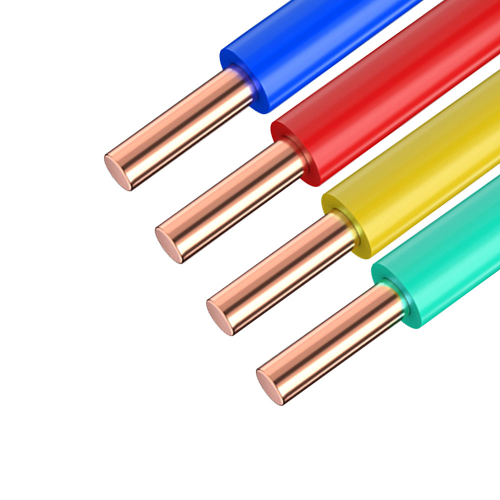 Fiber Optic Composite Cable Combining Power Cores and Optical FibersThis hybrid cable places copper power conductors and optical fiber units in one shared jacket, letting a single pull deliver both power and data—ideal for cranes, tunneling machines, and remote monitoring stations where separate routes are impractical.View Product →
The optical elements inside these hybrids obey every principle described above: total internal reflection, wavelength-dependent attenuation, and connector loss budgets. The jacket, meanwhile, must survive the environment, whether that means UV on exposed towers, oil in factory pits, or salt-laden air near coastlines. Where drive systems and inverters generate severe electrical noise, reinforced shielding around the cable keeps the surrounding hardware protected; the light itself is immune, but the terminations and electronics still benefit.
GDL23 fiber optic composite cable built for stable long-distance transmission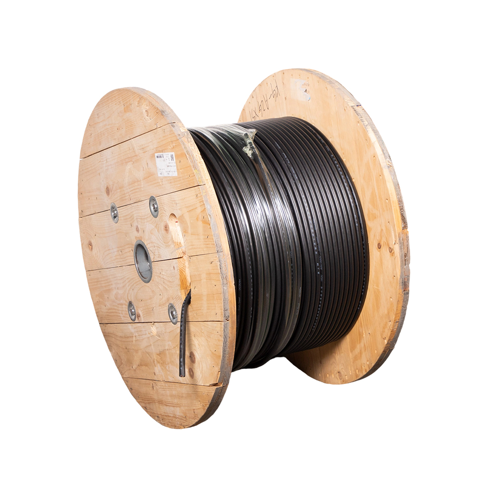 GDL23 Armored Fiber Optic Composite Cable for Direct BurialWith double-layer steel tape armor, water-blocking filling, and chemical-resistant sheathing, the GDL23 protects both optical and copper elements in harsh environments such as utility tunnels, subsidence zones, and areas with heavy electrical noise from drives and inverters.View Product →
On automated production lines, composite constructions are usually specified alongside other industrial cable families, and it helps to see them in the context of complete cable solutions for automation environments rather than as isolated components.
Fiber is not automatically the right answer, and treating it as such leads to overspending. Fiber wins decisively on distance, bandwidth per strand, EMI immunity, weight, and security, because tapping a glass fiber bends it and dims the signal, making intrusion detectable. Copper wins on connection cost, termination simplicity, and the ability to deliver power with data on the same pair, which is why copper still dominates the last few meters of most systems. Even in copper, signal quality is governed by insulation chemistry: PE dielectrics with a low dielectric constant reduce the capacitance that attenuates high-frequency signals, a principle covered further in our article on how low dielectric constant materials support stable transmission.
When you do specify fiber or a hybrid composite, check these points before comparing prices:
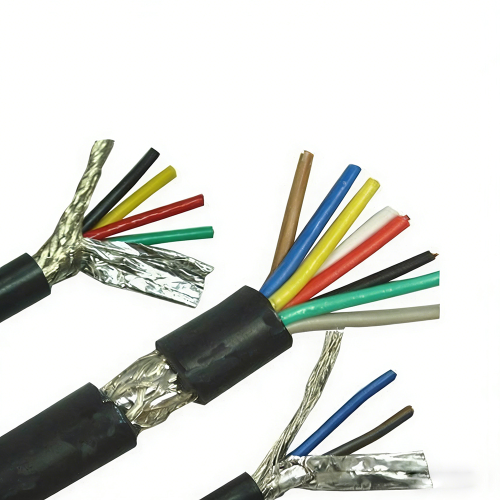 PRAP3 Shielded Triplet Sensor Signal CableFeaturing group and overall shielding for three-core balanced transmission, the PRAP3 keeps encoder and sensor signals clean on automated production lines where inverter noise is a concern, making it a relevant choice alongside composite cable specifications.View Product →
The working answer to "how does an optical cable work" fits in one sentence: a transmitter turns data into timed pulses of light, total internal reflection traps those pulses inside a glass core and carries them with minimal loss, and a receiver turns the light back into data. Everything else, from cladding chemistry and wavelength choice to jacket material, exists to serve that sentence. If you are planning a route that mixes power and communication, start from distance, environment, and electromagnetic conditions, then match the cable structure to those three facts. A manufacturer that designs both copper and optical constructions under one roof can usually propose a composite design that saves you a second pull entirely, and reviewing loss budgets and environmental requirements with the supplier before you finalize a specification is the cheapest insurance you can buy.

We firmly believe that good cables are not only a competition of materials, but also a reflection of craftsmanship, quality, and responsibility.

Links
Product
Send Inquiry
No. 29 Sankeshu Road, Xuanzhou District, Xuancheng City, Anhui Province, China
+86-18621104555/+86-563-2622999
 Electrical Cable Manufacturer
OEM/ODM Wire and Cable Solutions
Electrical Cable Manufacturer
OEM/ODM Wire and Cable Solutions
 English
 Español
 عربى
عربى
 русский