
Get more content that can help you
Content
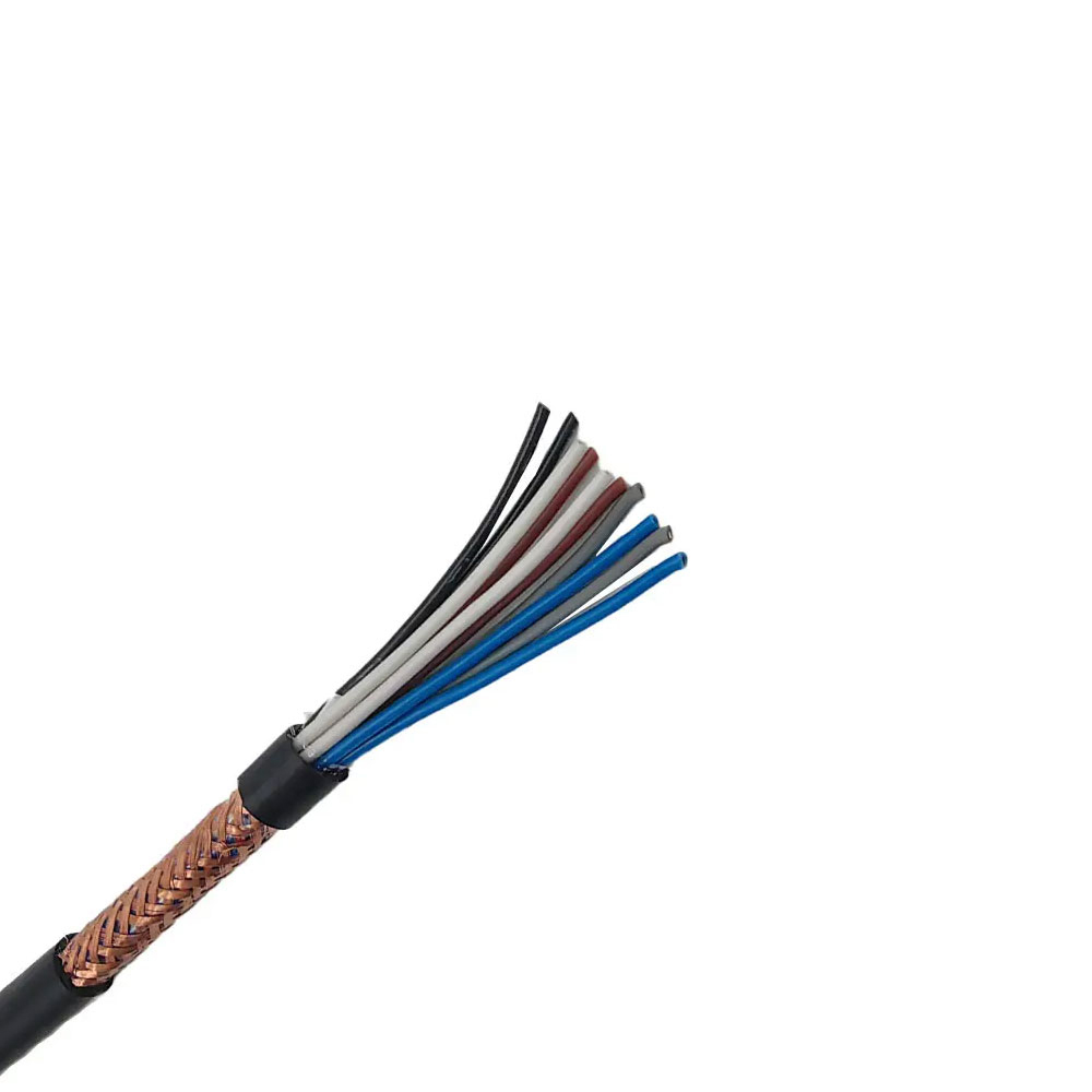
Modern automation, robotics, medical equipment, semiconductor manufacturing, and precision measurement systems increasingly depend on cable assemblies that can transmit reliable signals while moving continuously. In these applications, a conventional fixed-installation cable may suffer from conductor fatigue, excessive capacitance, signal distortion, electromagnetic interference, or premature sheath wear. The PRVZP-1 High-Flexibility Fiber Optic Composite Cable is designed to address these challenges through ultra-fine stranded conductors, a low-capacitance electrical structure, pair-level shielding, overall shielding, and an extra-flexible construction.
Although the product is identified as a fiber optic composite cable, the supplied construction and electrical parameters describe a highly flexible, shielded signal and communication cable intended for precision electronic systems. Its design combines twisted-pair signal transmission with robust mechanical performance, making it appropriate for applications where repeated movement and stable data transmission are equally important. Typical applications include robot joint sensors, high-precision encoders, medical instrument connections, semiconductor equipment, precision measuring instruments, and high-speed data acquisition systems.
The cable is manufactured by Anhui Zhishang Cable Technology Co., Ltd., a Chinese cable producer that integrates research and development, manufacturing, testing, sales, and customized cable design. The company operates a production base of approximately 5,000 square meters, uses multiple automated production lines, and supports both standard products and OEM/ODM projects based on customer drawings, samples, or technical requirements.
In a stationary electrical installation, a cable generally remains in one position after installation. The main design priorities are voltage rating, insulation resistance, temperature performance, and protection against environmental exposure. A cable installed inside a robot arm, moving medical platform, automatic inspection machine, or semiconductor tool faces a much more demanding operating condition.
Repeated bending causes mechanical stress in the conductor strands, insulation, shielding layers, fillers, and outer sheath. If the conductor is not sufficiently flexible, individual strands can break gradually. If the shielding structure is too rigid, it may crack or lose electrical continuity. If the sheath does not resist abrasion, it may become damaged where the cable repeatedly contacts a guide, drag chain, pulley, or machine frame.
Signal transmission creates another group of requirements. Precision sensors and encoders can generate low-level signals that are vulnerable to electromagnetic interference. Excessive working capacitance can alter signal shape, increase transmission loss, and reduce the available operating distance. Crosstalk between adjacent pairs can also reduce measurement accuracy or cause communication errors.
The PRVZP-1 is designed around these combined mechanical and electrical demands. Its ultra-fine stranded tinned copper conductor supports frequent movement, while its optimized capacitance design helps reduce signal distortion. Pair-level aluminum-polyester composite tape shielding, individual tinned copper drain wires, and an overall tinned copper braid provide multiple layers of protection against external and internal interference.
PRVZP-1 is an ultra-flexible sensor signal cable with a rated voltage of 300/300 V. It is available in conductor cross-sections from 0.14 mm² to 0.5 mm² and can be produced with between two and thirty-two cores. The core arrangement uses a twisted-pair structure, which supports balanced signal transmission and helps limit electromagnetic coupling between circuits.
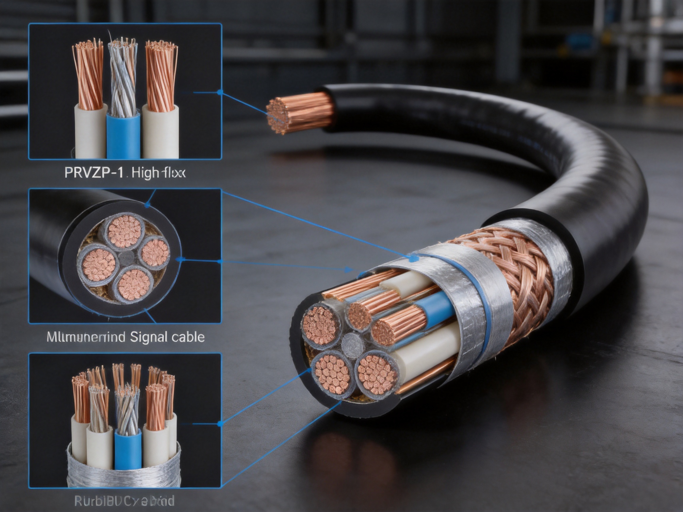
The cable uses stranded tinned copper conductors and polyethylene insulation. The individual insulated conductors are organized into pairs, with each pair protected by aluminum-polyester composite tape and a tinned copper drain wire. An overall tinned copper braid is then applied before the outer PVC sheath is installed. This layered construction is intended to preserve signal quality while providing mechanical stability and environmental protection.
The product is available with a gray or black sheath. Standard designs are suitable for fixed installation and flexible installation within the specified temperature and bending-radius limits. For applications involving repeated motion, the supplier identifies a bending life of at least eight million cycles, making the cable suitable for equipment that operates continuously or performs high-frequency movements.
Product characteristic | Specification |
Product designation | PRVZP-1 |
Product type | High-flexibility shielded sensor and communication cable |
Conductor | Stranded tinned copper, ultra-fine stranding |
Cross-section range | 0.14 mm² to 0.5 mm² |
Number of cores | 2 to 32 cores, twisted-pair structure |
Rated voltage | 300/300 V |
Insulation material | Polyethylene |
Sheath material | Polyvinyl chloride |
Characteristic impedance | 100 Ω ±8 Ω |
Signal transmission rate | Supports digital signals up to 10 Mbps |
Flexible-installation temperature | -20°C to +70°C |
Fixed-installation temperature | -40°C to +70°C |
Minimum bending radius | At least 6 times the cable outer diameter for flexible installation |
Specified bending life | At least 8 million cycles |
PRVZP-1 High compatibility Fiber Optic Composite Cable
The conductor is one of the most important elements in a continuously flexing cable. A large solid conductor may provide good electrical conductivity in a fixed installation, but it does not normally provide the mechanical performance required for repeated bending. A stranded conductor divides the bending stress across many fine wires, allowing the conductor to flex more easily.
PRVZP-1 uses ultra-fine stranded tinned copper conductors. The fine-stranding approach improves flexibility and reduces the concentration of mechanical stress at any single point. It also helps the cable achieve a smaller practical bending radius than a comparable cable using a rigid conductor structure.
The tin coating provides an additional layer of protection for the copper. Tinned copper is particularly useful where the cable may encounter humidity, oxidation, or demanding industrial conditions. The coating helps preserve conductor integrity and supports reliable termination during cable assembly and maintenance.
For robotic joints and moving machine axes, conductor fatigue is a major cause of cable failure. Every operating cycle can apply tensile, compressive, and torsional forces to the cable. When the conductors are stranded appropriately and the cable is routed according to its bending requirements, the mechanical load is distributed more evenly. This is a key reason the product is specified for a bending life of at least eight million cycles.
It is important to recognize that the stated bending life depends on installation conditions. The cable should not be twisted beyond its design capability, compressed by improper clamps, or forced into a bend smaller than the specified minimum. Correct routing, suitable cable guides, and proper strain relief are necessary to achieve the expected service life.
In sensor and data-acquisition systems, the cable is part of the electrical circuit rather than a passive accessory. The cable's capacitance, impedance, attenuation, and shielding can influence the performance of the complete system. A cable with excessive capacitance may load the signal source, slow signal transitions, and reduce the accuracy of high-speed or high-precision measurements.
PRVZP-1 uses an optimized low-capacitance design. Its working capacitance is specified at no more than 75 nF/km, while capacitance unbalance is specified at no more than 40 pF/100 m at 1 kHz. These characteristics help maintain a more consistent electrical environment across the twisted pairs.
The stated characteristic impedance is 100 Ω ±8 Ω. This impedance is widely used in balanced communication and data-transmission systems. Maintaining impedance within a controlled range helps reduce reflections and signal distortion, especially when the cable is connected to compatible transmitters, receivers, sensors, or data-acquisition devices.
The cable is specified for attenuation of no more than 1.1 dB/100 m at 1 MHz and supports digital signals up to 10 Mbps. Actual transmission performance depends on cable length, connector quality, equipment design, installation conditions, temperature, and the signal protocol being used. Nevertheless, the electrical design provides a suitable foundation for stable transmission in industrial measurement and communication applications.
Low capacitance is especially valuable in encoder and sensor circuits. An encoder may produce rapid transitions that must be recognized correctly by the control system. If the cable introduces excessive capacitance or distortion, the receiving equipment may interpret the signal incorrectly. The PRVZP-1 design seeks to reduce this risk while maintaining flexibility for moving applications.
Industrial equipment frequently contains motors, variable-frequency drives, switching power supplies, relays, solenoids, transformers, and high-current conductors. These components can generate electromagnetic fields that interfere with sensitive sensor and communication signals. Shielding is therefore essential when a cable is routed near power circuits or installed inside electrically noisy equipment.
PRVZP-1 uses a double-shielding structure. Each twisted pair is protected by an aluminum-polyester composite tape shield and a dedicated tinned copper drain wire. An overall tinned copper braid is then applied around the cable assembly. This arrangement provides both pair-level and overall protection.
The individual pair shield helps limit interference between signal pairs. It also reduces the possibility that one pair will affect another when several low-level circuits share the same cable. The overall braid provides a broader barrier against external electromagnetic fields and supports a continuous grounding path when correctly terminated.
The supplied technical information specifies crosstalk attenuation of at least 80 dB at 1 MHz and a shielding attenuation factor of no more than 0.5 at 1 MHz. These values indicate that the cable is intended for applications where signal purity and interference control are important.
Shielding performance depends not only on the cable itself but also on installation practice. The drain wire and braid should be terminated correctly. Grounding arrangements should be designed to suit the system architecture. Connectors, backshells, cable glands, and cabinet entry points should preserve shielding continuity. A high-performance shielded cable can lose much of its advantage if the shield is interrupted or connected incorrectly.
Moving equipment exposes cables to more than bending. Cables may rub against machine components, experience vibration, encounter lubricants, and be exposed to dust or humidity. The PRVZP-1 uses a PVC outer sheath designed to provide protection against general mechanical wear and industrial handling.
The product is specified to pass a 100,000-cycle reciprocating abrasion test. This characteristic is relevant for cables installed in moving machinery, guided tracks, and equipment where the cable may repeatedly contact a support surface. The specified tensile strength is at least 12 N/mm², offering additional mechanical stability during handling and installation.
The cable is also specified to pass a light-degree oil immersion test according to ISO 1817. This supports use in machinery environments where the cable may encounter limited exposure to lubricating oil or industrial contamination. The actual suitability of the cable should be confirmed when the installation involves aggressive chemicals, prolonged immersion, high concentrations of oil, or unusual fluids.
The fixed-installation temperature range is -40°C to +70°C. For flexible installation, the specified range is -20°C to +70°C. These two ranges reflect the different mechanical requirements of stationary and moving service. At lower temperatures, polymer materials may become less flexible, so the cable should be selected and routed according to the actual operating temperature.
Robotic equipment depends on reliable cable routing. A robot joint may rotate, bend, or move repeatedly throughout every production shift. Sensor cables installed inside the joint must follow the movement without excessive force or loss of signal quality.
PRVZP-1 is suitable for robot joint sensors, feedback devices, encoders, and other low-voltage signal circuits where a small bending radius and high cycle life are required. Its flexible conductor structure allows it to follow the movement of a robotic axis, while its shielded twisted-pair design helps protect feedback signals from motor and drive interference.
In automated assembly equipment, the cable may connect proximity sensors, inspection cameras, position sensors, and control modules. The cable can be selected with different numbers of cores and cross-sectional areas to support various equipment configurations. A multi-core version can simplify routing by combining several related signals in one cable assembly.
For best results, designers should consider the robot manufacturer's recommended cable routing method, torsion requirements, travel length, acceleration, and movement frequency. The eight-million-cycle bending specification is a significant advantage, but it should not be interpreted as unlimited torsional performance unless the specific cable version has been tested for torsion as well as bending.
Medical instruments and laboratory systems often require compact, low-noise cable assemblies. A cable may connect a movable probe, imaging module, measurement head, or patient-contact instrument to a stationary control unit. In these applications, the cable must move smoothly without generating excessive electrical noise or mechanical resistance.
The ultra-fine conductors and flexible construction of PRVZP-1 can support mobile connections in medical instruments and precision measuring devices. The low-capacitance design helps protect signal timing and waveform quality, while the double shielding helps reduce interference from motors, displays, power converters, and nearby electronic equipment.
Product selection for medical equipment must consider the complete regulatory and biocompatibility requirements of the finished device. The cable specifications provided for PRVZP-1 do not by themselves establish suitability for direct patient contact, sterilization, medical-grade biocompatibility, or use inside life-support equipment. System manufacturers should complete their own validation and compliance assessment.
Semiconductor manufacturing equipment often combines precision motion systems, vacuum mechanisms, temperature-control units, sensors, robotic handling systems, and high-speed control electronics. Cable assemblies may need to pass through narrow spaces and move repeatedly while maintaining stable signal performance.
PRVZP-1 can be considered for sensor and communication connections in semiconductor tools where the environmental conditions match the product specifications. Its controlled impedance, low capacitance, pair shielding, and overall braid are useful for signal circuits that operate near switching equipment or precision drives.
Precision measurement and high-speed data acquisition systems also benefit from controlled electrical characteristics. The cable's specified attenuation, crosstalk performance, and 100 Ω nominal impedance help system designers evaluate it during the initial design stage. Before production use, the cable should be tested with the actual instruments, connectors, signal frequencies, and cable lengths required by the application.
The supplied product information identifies several marine-oriented advantages, including resistance to salt spray corrosion, oil contamination, mechanical wear, and electromagnetic interference. These characteristics are relevant to shipboard electrical systems, engine rooms, commercial vessels, and engineering vessels where humidity, vibration, oil, and salt-laden air may be present.
Tinned copper conductors are beneficial in humid environments because the coating helps reduce oxidation of the copper surface. The protective sheath and shield structure provide additional separation from moisture and mechanical contact. When installed with suitable glands and terminations, a shielded cable can support stable communication and control signals in demanding equipment spaces.
The supplied information also describes the product as having low-smoke and halogen-free marine fire-safety characteristics. However, the technical table identifies PVC as the sheath material. Because PVC is not generally classified as halogen-free, purchasers requiring low-smoke, zero-halogen, marine fire-performance certification should request formal test reports and verify the exact material construction before ordering. A halogen-free version may require a different sheath compound and should be treated as a customized or separately specified product.
Marine applications require careful attention to classification society rules, flame propagation, smoke density, toxicity, oil resistance, water resistance, and fire survival. The PRVZP-1 product information supports discussion of marine suitability, but project-specific approval should be confirmed through the relevant certificates and technical documentation.
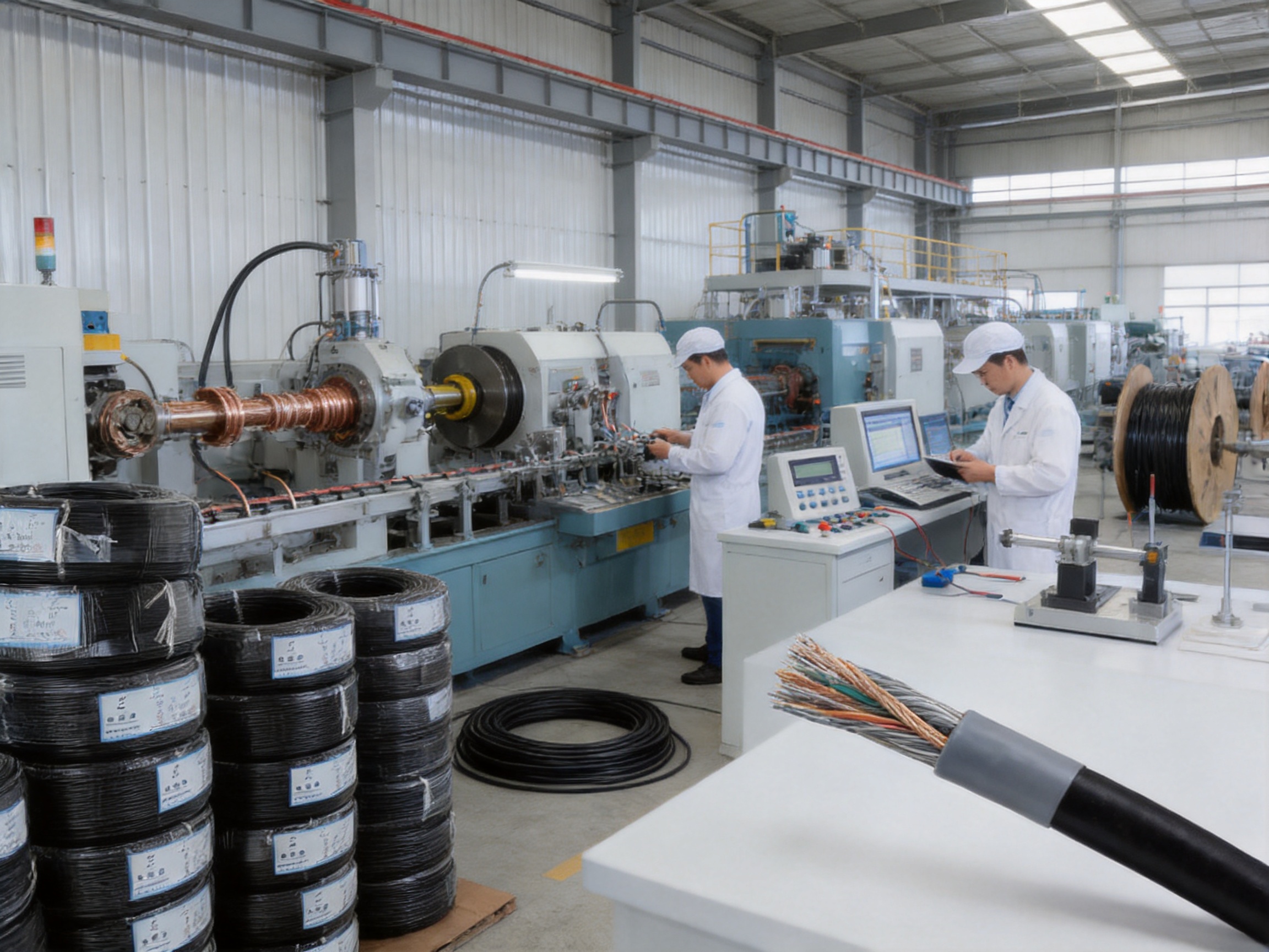
The performance of a flexible, shielded signal cable depends on manufacturing consistency. Small variations in conductor stranding, insulation thickness, pair geometry, shielding overlap, braid coverage, and sheath extrusion can influence both mechanical life and signal performance. For this reason, advanced manufacturing processes are central to the product's value.
Anhui Zhishang Cable Technology Co., Ltd. integrates product development, production, testing, and sales. The company operates a modern production base of approximately 5,000 square meters and has more than 50 employees, including quality engineers and research and development technicians with more than ten years of industry experience.
The company reports the use of ten automated production lines and a monthly production capacity of up to ten million meters. Automated equipment can improve production repeatability by controlling conductor stranding, insulation extrusion, cable formation, shielding application, and outer sheath extrusion. Automation also helps reduce variation between production batches when equipment is properly calibrated and maintained.
Production begins with the selection and preparation of copper conductors. For PRVZP-1, tinned copper strands are formed into an ultra-fine stranded conductor. Stranding parameters must be controlled so that the conductor remains flexible without becoming loose or unstable. Tension control is important because excessive tension can reduce flexibility, while insufficient tension may affect dimensional consistency.
The conductor cross-section is verified according to the selected product specification. Electrical resistance, surface quality, tin coating condition, and strand integrity are important inspection points. Consistent conductor quality supports stable current-carrying performance and reliable termination.
Polyethylene insulation is extruded over the conductors. The specified insulation thickness ranges from 0.15 mm to 0.3 mm, depending on the design. Extrusion temperature, line speed, cooling conditions, and concentricity must be managed carefully to maintain a uniform insulation layer.
Insulation quality affects dielectric strength, capacitance, impedance, flexibility, and long-term reliability. Excessive thickness can increase cable diameter and stiffness, while insufficient or uneven thickness may reduce electrical safety. Online dimensional monitoring and electrical spark testing are commonly used to identify defects during insulation production.
After insulation, the cores are arranged into twisted pairs. The twist geometry contributes to balanced transmission and helps control electromagnetic coupling. The twisting pitch must be maintained within the intended range to preserve the electrical characteristics of the design.
Different pairs may use controlled lay lengths to reduce pair-to-pair coupling. Careful pair formation also helps prevent excessive deformation of the insulated cores. This is particularly important for low-capacitance designs, where physical geometry directly influences capacitance and impedance.
Each pair is protected with aluminum-polyester composite tape and a tinned copper drain wire. The tape application process must provide consistent coverage and appropriate overlap. The drain wire must remain in reliable contact with the conductive side of the shielding system so that the pair shield can be terminated effectively.
Improper tape tension can cause wrinkles, gaps, or excessive rigidity. Excessive tension may limit flexibility, while inadequate coverage may reduce shielding performance. Manufacturing control is therefore necessary to balance electrical protection with the mechanical requirements of a moving cable.
After the pairs are assembled, an overall tinned copper braid is applied. Braid coverage, angle, tension, and continuity are important factors in overall shielding effectiveness. The braid must provide protection without making the cable unnecessarily stiff.
The final PVC sheath is extruded over the completed cable core. Sheath thickness is specified at 0.6 mm to 1.0 mm. The extrusion process must maintain a smooth surface, consistent diameter, adequate adhesion, and correct color. Gray and black are the standard sheath colors identified for this product.
Finished cable inspection may include outer-diameter measurement, visual inspection, conductor continuity, insulation resistance, voltage testing, shield continuity, dimensional checks, and selected mechanical or electrical performance tests. Product test reports can be provided for defined models according to customer requirements.
One of the main advantages of working with an integrated cable manufacturer is the ability to coordinate product design, production, testing, and technical support through one supply chain. This can simplify communication when a customer requires a special conductor size, core count, shielding structure, sheath material, color, marking, or packaging format.
Anhui Zhishang Cable Technology Co., Ltd. supports OEM and ODM development based on customer drawings or samples. Technical engineers can assist with product selection and customized cable design according to the movement pattern, signal type, voltage, environment, installation space, and expected service life of the application.
The company states that it follows national standards, relevant international standards, and industry benchmarks. It also emphasizes full-core, full-length, pure copper specifications, product test reports, and warranty support for standard cable models. These points are relevant to industrial buyers that require traceability and consistent procurement quality.
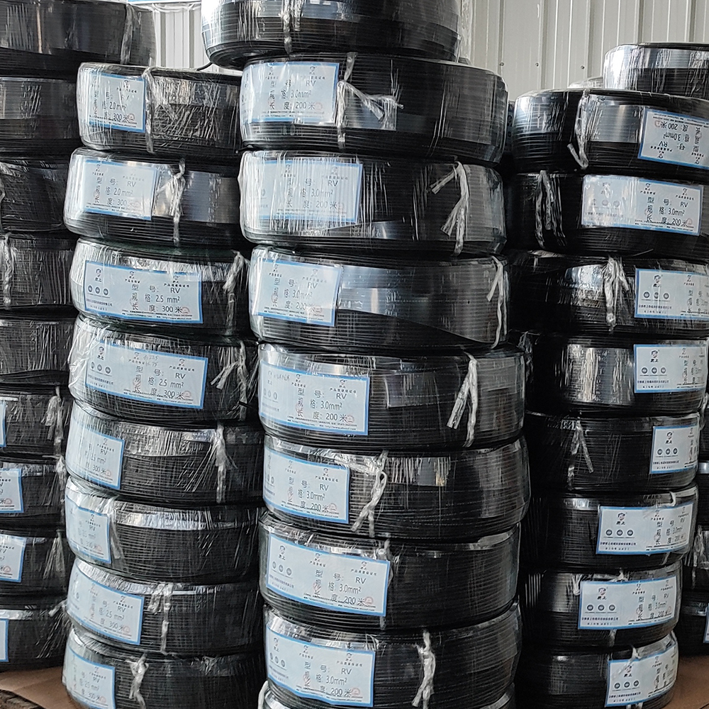
Standard products may be stocked for faster shipment, while customized products typically require a lead time of approximately seven to twenty days. Actual lead time depends on the design, material availability, order quantity, testing requirements, and production schedule. The company's reported monthly capacity of up to ten million meters provides a foundation for both regular supply and larger project requirements.
Its customer base and market experience cover industrial automation, weak-current engineering, intelligent manufacturing, appliance equipment, power engineering, and related applications. The company also reports sales into the United States, Canada, Australia, Japan, and parts of Eurasia. International supply requires attention to packaging, documentation, labeling, electrical standards, and project-specific compliance.
Compared with a basic flexible control cable, PRVZP-1 offers a more specialized electrical structure for precision signals. A conventional flexible cable may provide adequate movement performance but lack controlled impedance, pair-level shielding, low capacitance, or defined crosstalk characteristics.
Compared with an ordinary shielded multi-core cable, PRVZP-1 provides additional protection through individual pair shields combined with an overall braid. This can be advantageous when multiple sensor or communication circuits share one cable and must remain electrically separated.
Compared with a fixed-installation data cable, PRVZP-1 offers a much stronger focus on repeated movement. Its ultra-fine stranded conductors, extra-flexible construction, abrasion resistance, and specified eight-million-cycle bending life make it more suitable for moving machinery.
Compared with a cable designed only for high-speed data transmission, PRVZP-1 balances signal performance with mechanical flexibility. It supports digital signals up to 10 Mbps, has a nominal 100 Ω impedance, and is designed for applications where the cable must move continuously rather than remain in a data cabinet.
Design requirement | PRVZP-1 design response | Application benefit |
Frequent bending | Ultra-fine stranded conductors and extra-flexible construction | Improved movement capability and reduced conductor fatigue |
Signal interference | Pair-level tape shielding and overall tinned copper braid | Improved protection against external noise and crosstalk |
Signal distortion | Low-capacitance design and controlled impedance | More stable sensor and communication transmission |
Machine abrasion | PVC outer sheath and specified abrasion performance | Improved resistance to repeated rubbing |
Humid environments | Tinned copper conductors and protective sheath | Better resistance to oxidation and environmental exposure |
Project customization | OEM/ODM support and multiple core and cross-section options | Better integration with customer equipment |
Installation quality has a direct impact on cable life. During routing, the cable should not be bent below six times its outer diameter for flexible installation or four times its outer diameter for fixed installation. The actual outer diameter should be confirmed for the selected core count and construction.
The cable should be supported so that its weight does not create continuous tension at connectors or terminals. Strain relief should be positioned close enough to the termination to prevent excessive movement at the contact point, but it should not crush the sheath or deform the cable core.
In moving applications, the cable should follow a smooth, controlled path. Sharp edges, tight corners, unsupported loops, and irregular drag-chain movement should be avoided. The cable should not be twisted during installation unless the selected design has been specifically approved for torsional movement.
Shield termination should be planned before installation. If the pair shields and overall braid are not connected according to the system's grounding strategy, the expected electromagnetic protection may not be achieved. Connectors should be selected to preserve the cable's shielding structure and support the required number of cores.
For marine or humid environments, cable glands and entry seals should be selected to prevent moisture ingress. Cable ends should be protected during storage and installation. Unsealed cable ends can allow moisture to enter the construction, particularly when the cable is exposed to condensation or salt spray.
The first selection factor is the number of cores. A two-core or small-core-count version may be suitable for a single sensor circuit, while a higher-core-count version can combine several signal pairs in one assembly. The required number of pairs should be determined from the equipment wiring diagram, including spare circuits where appropriate.
The second factor is conductor cross-section. Smaller conductors support compact and flexible designs, while larger cross-sections may be selected when the circuit requires greater current capacity or increased mechanical strength. The chosen cross-section should match the load, voltage drop, termination method, and equipment manufacturer's requirements.
The third factor is the movement profile. Designers should document the bending radius, travel length, cycle frequency, acceleration, vibration, and any torsion. A cable designed for repeated bending may not automatically be suitable for continuous torsion or robotic dress-pack applications without further testing.
The fourth factor is the environment. Temperature, oil, water, salt spray, chemicals, abrasion, fire performance, smoke requirements, and installation location should all be reviewed. If a low-smoke, halogen-free, flame-retardant, or marine-certified construction is required, the exact product version and certification should be confirmed before purchase.
The fifth factor is the signal protocol. The cable's nominal impedance and transmission characteristics should be matched to the transmitter, receiver, encoder, network, or data-acquisition system. Testing with the complete signal chain is recommended for critical or high-speed applications.

Parameter | PRVZP-1 value |
Conductor material | Stranded tinned copper |
Conductor structure | Ultra-fine stranding |
Cross-section | 0.14 mm² to 0.5 mm² |
Core count | 2 to 32 cores |
Pair structure | Twisted pair |
Rated voltage | 300/300 V |
Test voltage | 1.5 kV AC for one minute |
Insulation | Polyethylene |
Insulation thickness | 0.15 mm to 0.3 mm |
Pair shield | Aluminum-polyester composite tape with tinned copper drain wire |
Overall shield | Tinned copper braid |
Sheath | PVC |
Sheath thickness | 0.6 mm to 1.0 mm |
Temperature, fixed installation | -40°C to +70°C |
Temperature, flexible installation | -20°C to +70°C |
Minimum bending radius, fixed | At least four times the cable outer diameter |
Minimum bending radius, flexible | At least six times the cable outer diameter |
Insulation resistance | At least 200 MΩ·km at 20°C |
Capacitance unbalance | Up to 40 pF/100 m at 1 kHz |
Characteristic impedance | 100 Ω ±8 Ω |
Working capacitance | Up to 75 nF/km |
Attenuation | Up to 1.1 dB/100 m at 1 MHz |
Crosstalk attenuation | At least 80 dB at 1 MHz |
Bending life | At least 8 million cycles under flexible installation conditions |
Signal rate | Up to 10 Mbps digital signal support |
Sheath colors | Gray or black |
PRVZP-1 is designed for flexible sensor, encoder, control, and communication connections where the cable must withstand repeated bending while maintaining stable signal transmission. It is particularly suited to robotic equipment, precision instruments, medical equipment, semiconductor tools, and automated machinery.
It is designed for flexible installation and is specified for a bending life of at least eight million cycles. The cable must be installed within the stated temperature and bending-radius limits. Continuous torsion, high acceleration, or special robotic movements should be reviewed with the manufacturer before final selection.
Each twisted pair has an aluminum-polyester composite tape shield and a tinned copper drain wire. The entire cable assembly is also protected by an overall tinned copper braid. This two-level structure helps reduce interference between pairs and protects the complete cable from external electromagnetic noise.
The supplied specification identifies support for digital signals up to 10 Mbps. Actual performance depends on cable length, signal protocol, connectors, grounding, equipment compatibility, installation quality, and environmental conditions.
The rated voltage is 300/300 V. The stated test voltage is 1.5 kV AC for one minute. The cable should be used only within the voltage, temperature, and installation requirements of the selected design.
The product information identifies resistance to oil, abrasion, salt spray corrosion, and humid environments. However, outdoor and marine projects may require specific UV, water-blocking, flame, smoke, halogen-free, or classification-society certifications. These requirements should be confirmed against the exact cable version and supporting test documentation.
The supplied product information mentions low-smoke and halogen-free marine characteristics, while the technical table specifies a PVC sheath. Because PVC is generally a halogen-containing material, customers requiring halogen-free performance should request confirmation of the exact sheath compound and relevant test reports. A special low-smoke, zero-halogen version may be required.
Standard configurations range from two to thirty-two cores, with twisted-pair construction. Other arrangements, conductor sizes, shielding structures, colors, markings, and sheath materials may be possible through OEM or ODM development, subject to technical review and production requirements.
Customers should provide the required core count, conductor cross-section, voltage, signal type, data rate, cable length, bending radius, movement pattern, cycle frequency, temperature, environmental exposure, connector requirements, sheath color, applicable standards, and expected annual quantity. Drawings or samples can also assist the engineering team.
Standard products may be available from stock for fast shipment. Customized products typically require approximately seven to twenty days, although the actual lead time depends on design complexity, material availability, order quantity, testing requirements, and production scheduling.
The cable should be routed smoothly, protected from sharp edges, supported with suitable strain relief, and installed at or above the required minimum bending radius. In moving applications, the cable should not be crushed, twisted beyond its design capability, or forced into an irregular path. Shield termination should be planned to maintain electrical continuity.
PRVZP-1 combines ultra-fine stranded conductors, low-capacitance electrical design, controlled 100 Ω impedance, pair-level shielding, overall braid shielding, abrasion resistance, and a specified high bending life. This combination is intended for precision signals in moving equipment rather than general fixed control wiring alone.
PRVZP-1 is a specialized high-flexibility cable for applications that demand both mechanical endurance and reliable signal transmission. Its ultra-fine stranded tinned copper conductors support repeated movement, while its polyethylene insulation, twisted-pair structure, low-capacitance design, and controlled impedance help preserve electrical performance.
The double-shielding structure is one of the product's principal advantages. Individual pair shields help reduce crosstalk, and the overall tinned copper braid provides additional protection against external electromagnetic interference. These characteristics make the cable suitable for robot sensors, encoders, precision instruments, medical equipment, semiconductor machinery, and high-speed data acquisition systems.
The cable's specified bending life of at least eight million cycles, abrasion resistance, light oil resistance, and flexible temperature range provide a strong foundation for industrial use. Correct installation remains essential, particularly in applications involving continuous movement, small bending radii, or demanding environmental conditions.
The manufacturer's integrated R&D, production, testing, and customization capabilities further strengthen the product offering. With automated production lines, experienced technical personnel, OEM/ODM support, standard product availability, and international market experience, the company can serve both standard procurement requirements and specialized cable development projects.
For customers selecting PRVZP-1, the most important next step is to match the exact cable configuration to the application. Core count, cross-section, signal protocol, cable length, movement profile, environmental exposure, shielding termination, fire-performance requirements, and applicable certifications should all be confirmed before production approval. When these factors are properly evaluated, PRVZP-1 can provide a practical and reliable solution for precision signal transmission in flexible industrial systems.
1. Product technical information for PRVZP-1 High-Flexibility Fiber Optic Composite Cable, including conductor, insulation, shielding, electrical, mechanical, and environmental specifications.
2. ISO 1817, Rubber, vulcanized or thermoplastic — Determination of the effect of liquids.
3. General principles of electrical cable design, conductor stranding, insulation extrusion, shielding, impedance control, and signal-integrity engineering.
4. Industrial automation cable installation practices for flexible routing, bending-radius control, strain relief, drag-chain use, and electromagnetic compatibility.
5. Technical principles of twisted-pair transmission, capacitance balance, characteristic impedance, attenuation, crosstalk, and electromagnetic shielding.
6. Manufacturer-provided company information concerning production facilities, automated manufacturing lines, OEM/ODM capability, quality assurance, technical support, and international supply.
7. Project-specific standards and certification requirements applicable to marine, medical, semiconductor, robotics, and industrial automation cable installations.

We firmly believe that good cables are not only a competition of materials, but also a reflection of craftsmanship, quality, and responsibility.

Links
Product
Send Inquiry
No. 29 Sankeshu Road, Xuanzhou District, Xuancheng City, Anhui Province, China
+86-18621104555/+86-563-2622999
 Electrical Cable Manufacturer
OEM/ODM Wire and Cable Solutions
 English
 Español
 عربى
 русский