
Get more content that can help you
Content
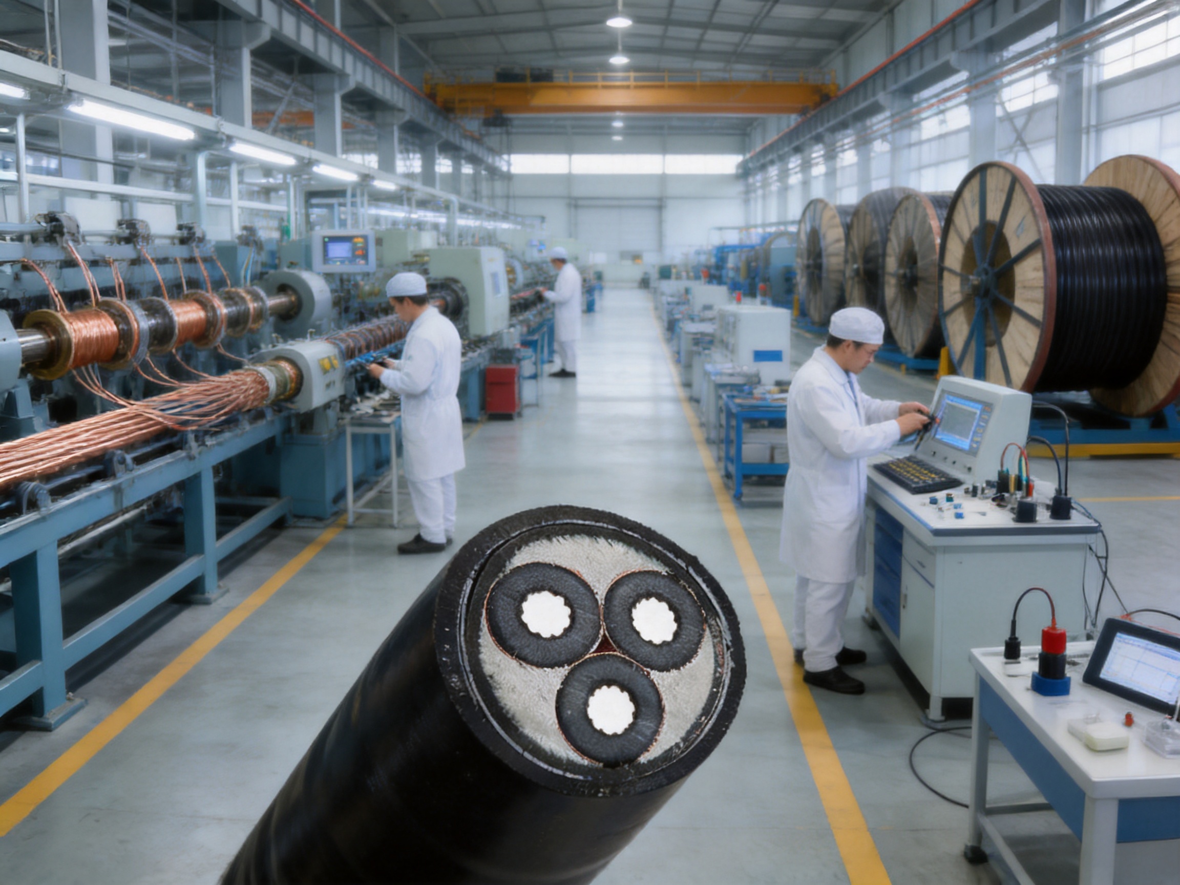
Modern power infrastructure increasingly requires cables that can perform reliably under more than ordinary electrical loading. In many projects, the cable must also withstand pulling forces, vibration, compression, impact, moisture, corrosion, difficult routing, and long-term exposure to demanding environmental conditions. A conventional unarmored power cable may provide satisfactory electrical transmission, yet fail to offer the mechanical protection or tensile strength required for vertical shafts, steep slopes, bridge suspensions, underwater routes, mining systems, and other fixed installations where the cable is subjected to sustained longitudinal tension.
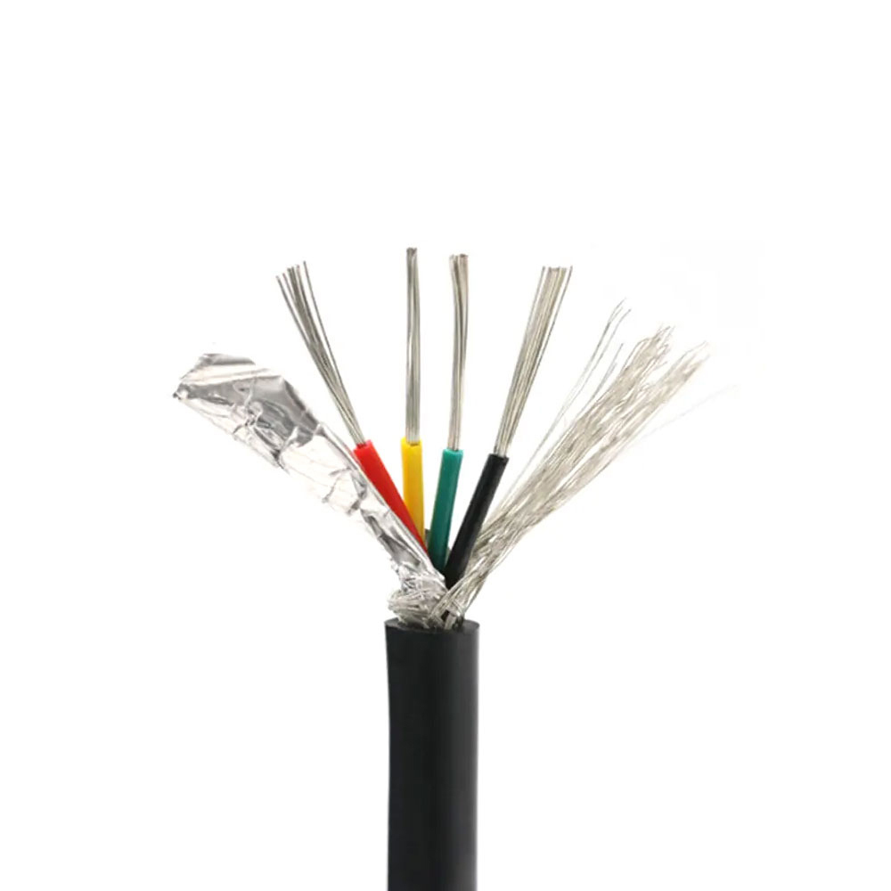
The YJV32 high-conductivity high-voltage cable is designed for precisely these demanding applications. It combines a copper conductor, cross-linked polyethylene insulation, a wrapped copper tape shield, fine round steel wire armor, and a protective outer sheath. This construction creates a power cable with strong electrical performance and enhanced mechanical resistance. The steel wire armor is particularly important because it helps the cable tolerate tensile loads while also improving resistance to compression, impact, rodent damage, and installation-related stress.
With rated voltage options extending from 0.6/1 kV to 12/20 kV, the cable can support a broad range of low-voltage, medium-voltage, and higher-voltage distribution requirements, subject to the applicable design and installation standards. Its XLPE insulation is rated for continuous operation at up to 90°C, while the conductor can withstand a short-circuit temperature of up to 250°C for a maximum of five seconds. These characteristics make the cable suitable for industrial power distribution, infrastructure projects, mine hoisting systems, utility networks, tunnels, pipelines, bridges, and other installations where electrical reliability and mechanical durability must work together.
Manufactured by Anhui Zhishang Cable Technology Co., Ltd., the product benefits from an integrated approach covering research and development, conductor processing, insulation extrusion, shielding, armoring, sheathing, inspection, customization, and technical support. The manufacturer operates modern production facilities of approximately 5,000 square meters, maintains ten automated production lines, and reports a monthly production capacity of up to ten million meters across its cable portfolio. This manufacturing platform supports both standard cable supply and OEM/ODM development based on customer drawings, samples, or project specifications.
The designation YJV32 identifies a structured power cable rather than a simple insulated conductor. In general application terminology, “YJ” refers to cross-linked polyethylene insulation, “V” identifies a polyvinyl chloride sheath, and “32” indicates a cable construction using fine steel wire armor with a protective sheath. Depending on the selected design, the cable may include an inner sheath made from PVC or polyethylene and an outer sheath made from PVC or a low-smoke zero-halogen flame-retardant polyolefin compound.
The defining engineering purpose of the YJV32 structure is to provide additional mechanical support where ordinary cables may be vulnerable. A standard unarmored cable is primarily designed to carry electrical current and tolerate the environmental conditions expected in a relatively protected route. By contrast, a fine steel wire armored cable is designed for situations in which the cable itself is exposed to mechanical forces during installation or operation.
Examples include a cable suspended over a bridge, routed through a vertical shaft, installed along a steep incline, lowered through a mine, or placed in an underwater or partially submerged route. In these applications, the cable’s own weight may create a continuous longitudinal load. Pulling during installation can add another significant force, while vibration, movement, and thermal expansion may produce repeated mechanical stress. The armor helps distribute these forces and protects the insulated cores from direct mechanical damage.
It is important to recognize that armor does not eliminate the need for correct cable support. Dedicated clamps, suspension fittings, cleats, rollers, pulling equipment, and termination systems must be selected according to the cable’s mass, diameter, route geometry, installation tension, and operating conditions. The YJV32 construction improves the cable’s tensile capability, but the complete installation system must still be engineered as a mechanical and electrical assembly.
The cable uses a copper conductor in compacted round or sector-shaped form. Copper is widely selected for high-performance power cables because it has low electrical resistivity, strong current-carrying capability, good thermal conductivity, and reliable compatibility with common cable accessories. These properties help reduce transmission losses and support efficient power delivery over short and long distribution routes.
A compacted conductor offers additional practical benefits. By reducing voids between individual wires, compaction helps produce a more efficient cross-sectional shape and can reduce the overall cable diameter compared with a loosely stranded conductor of equivalent electrical area. A compacted round conductor is useful for many single-core and multi-core designs, while a sector-shaped conductor can help optimize the geometry of multi-core cables.
The available cross-section range is listed as 1.5 mm² to 800 mm². The correct size depends on current demand, installation method, ambient temperature, grouping, voltage drop, short-circuit conditions, route length, and applicable national or project standards. A larger conductor is not automatically the best choice; cable selection should balance electrical requirements with bending radius, weight, installation equipment, terminal compatibility, and total project cost.
Cross-linked polyethylene insulation forms the primary dielectric layer around the conductor. Compared with many traditional thermoplastic insulation materials, XLPE provides a combination of high dielectric strength, low dielectric loss, good thermal stability, and strong long-term operating performance. These characteristics are valuable in high-voltage and medium-voltage power distribution, where insulation quality has a direct effect on service life and system reliability.
The cable is designed for a long-term conductor operating temperature of up to 90°C. Under short-circuit conditions, the conductor temperature may reach up to 250°C for a maximum duration of five seconds, provided the design and installation comply with the relevant standard and the fault-clearing system operates within the specified time. XLPE also supports stable performance under normal load cycles and helps reduce the risk of insulation deterioration caused by excessive thermal stress.
The insulation thickness complies with the requirements of GB/T 12706.1 for the applicable cable design. In practical manufacturing, maintaining consistent insulation thickness is essential. Uneven insulation can create localized electric stress, reduce dielectric reliability, and complicate quality control. Automated extrusion equipment, dimensional monitoring, process parameter control, and electrical testing are therefore important elements of a dependable production system.
A wrapped copper tape shield is provided around the insulated core assembly or individual insulated components according to the selected construction. The shield can help control the electric field, provide a controlled path for fault current, reduce electromagnetic interference, and support the safe operation of medium-voltage cable systems when properly bonded and grounded.
Shielding design must be coordinated with the system grounding arrangement, cable length, installation method, fault-current requirements, and termination accessories. A copper tape shield is not simply an additional metallic layer; it is part of the cable’s electrical protection system. Correct preparation of the shield at joints and terminations is necessary to maintain field control and prevent localized electrical stress.
The fine round steel wire armor is the defining mechanical component of the YJV32 construction. The armor creates a protective cage around the cable and improves resistance to tension, compression, impact, abrasion, and external interference. It can also provide additional resistance against rodent damage and accidental contact with tools or surrounding structures.
Fine round steel wires can conform closely to the cable’s shape while retaining flexibility appropriate for a fixed armored installation. The armor is especially useful in routes where the cable may experience longitudinal tension. Vertical shafts and steep slopes are typical examples, because gravity creates a continuous load that must be transferred safely through the support system. The armor also helps during controlled installation, when pulling forces are applied to move the cable into position.
Although the armor significantly strengthens the cable, it also increases cable weight, outer diameter, minimum bending radius, and material cost. Installers must avoid using inappropriate pulling methods or clamps that concentrate force on the sheath or individual armor wires. Dedicated suspension fittings and properly distributed support points are recommended for vertical or tension-bearing applications.
The cable may include an inner sheath made from PVC or polyethylene and an outer sheath made from PVC or low-smoke zero-halogen flame-retardant polyolefin. The inner sheath helps separate the armored layer from the insulated cores and provides an additional environmental and mechanical barrier. The outer sheath protects the completed cable from moisture, corrosion, abrasion, ultraviolet exposure, and general handling damage.
PVC is a practical sheath material for many outdoor, tunnel, pipeline, industrial, and utility applications. It offers useful resistance to moisture and corrosion and is available in a wide range of compound formulations. Where smoke emission and halogen content are major concerns, an LSZH flame-retardant outer sheath may be selected. This option is particularly relevant in enclosed public spaces, transportation facilities, control areas, and installations where smoke toxicity must be reduced.
The standard sheath color is black. Sheath thickness complies with the applicable GB/T 12706.1 requirements, while flame retardancy can be designed to meet GB/T 19666 Class A, B, or C. The appropriate grade should be selected according to the fire risk, route environment, building regulations, and project specification.

YJV32 High conductivity High-Voltage Cable
The following table summarizes the principal characteristics provided for the YJV32 cable. Final cable construction, electrical ratings, dimensions, and test requirements should be confirmed against the technical data sheet and project-specific order documentation.
| Item | Specification |
|---|---|
| Product type | YJV32 high-conductivity high-voltage power cable |
| Conductor | Copper, compacted round or sector-shaped |
| Cross-section range | 1.5 mm² to 800 mm² |
| Rated voltage options | 0.6/1 kV, 1.8/3 kV, 3.6/6 kV, 6/10 kV, 8.7/15 kV, and 12/20 kV |
| Insulation | Cross-linked polyethylene |
| Shielding | Wrapped copper tape shield |
| Armor | Fine round steel wire armor |
| Inner sheath | PVC or polyethylene |
| Outer sheath | PVC or LSZH flame-retardant polyolefin |
| Test voltage | 3.5U₀ AC for five minutes |
| Long-term operating temperature | Up to +90°C |
| Short-circuit temperature | Up to 250°C for five seconds |
| Insulation resistance | At least 1000 MΩ·km at 20°C |
| Minimum bending radius | Multi-core cable: 15 times the cable outer diameter |
| Minimum installation temperature | 0°C or above |
| Specified tensile strength | Withstands at least 8000 N tensile force |
| Flame-retardant performance | Available to GB/T 19666 Class A, B, or C |
| Standard sheath color | Black |
The copper conductor provides low electrical resistance, which helps reduce I²R losses during power transmission. Lower conductor resistance can improve energy efficiency and reduce heat generation under load. This is especially valuable in long-distance routes, high-load industrial systems, and installations where the cable operates continuously for many hours per day.
Compared with lower-conductivity conductor materials, copper can provide a more compact solution for the same current requirement. A compact copper conductor may simplify termination and help reduce the space required in cable trenches, switchgear compartments, junction boxes, and distribution panels. However, the final conductor size must always be selected through a complete electrical calculation rather than by material choice alone.
XLPE insulation supports reliable electrical performance over a broad operating range. Its low dielectric loss helps limit energy dissipation in the insulation, while its high dielectric strength supports safe operation at the specified voltage levels. The insulation system is particularly suitable for distribution circuits that require consistent performance over long service periods.
The combination of XLPE insulation and copper tape shielding also contributes to controlled electrical stress. In medium-voltage designs, this is essential because irregular field distribution can lead to partial discharge, accelerated insulation aging, and eventual breakdown. Consistent extrusion, clean material handling, and careful shielding are therefore as important as the nominal insulation material itself.
The stated short-circuit temperature limit of up to 250°C for five seconds indicates that the cable is designed to tolerate a temporary fault condition within the specified duration. This performance must be coordinated with conductor area, shield design, grounding arrangement, protective relay settings, and fault-clearing time. A cable’s short-circuit rating is not an independent number; it is part of the complete protection coordination study.
The available voltage range allows the same general cable family to serve different power distribution levels. Lower voltage configurations may be used in building services, industrial equipment, and local distribution. Higher voltage configurations can be considered for substations, utility networks, mine systems, and long-distance industrial feeders, subject to system design and applicable standards.
This range benefits project planners because it enables a consistent procurement relationship across several cable categories. Engineering teams can discuss conductor material, insulation, shielding, armor, sheath, testing, packaging, and documentation with one experienced manufacturer while selecting the voltage construction appropriate for each circuit.
The most significant advantage of the YJV32 design is its ability to support applications exposed to sustained tension. Fine steel wire armor helps transmit and distribute tensile forces along the cable length. This makes the cable more suitable than ordinary unarmored power cable for vertical shafts, steep gradients, bridge suspension routes, mine hoisting systems, and other fixed installations with substantial cable weight or pulling force.
The specified tensile performance of at least 8000 N provides a useful reference point for project planning. Nevertheless, engineers must compare this value with the actual installation tension, safety factor, cable length, route elevation, pulling method, temperature, and support arrangement. Where the cable is installed vertically, the cable weight between support points can become more important than the pulling force used during initial installation.
Industrial and infrastructure routes can expose cables to accidental impact from equipment, falling objects, construction tools, vehicle movement, or shifting soil. The armored layer helps shield the inner electrical components from such forces. It also improves resistance to compression in direct-buried routes, cable trenches, underground passages, and areas where other materials may press against the cable.
Armor does not make the cable indestructible. Excessive crushing, sharp bends, uncontrolled dragging, or improper storage can still damage the sheath, armor, insulation, or conductor. Appropriate handling equipment and installation procedures remain necessary. The advantage is that the cable has a stronger mechanical structure and a larger margin of protection than a comparable unarmored construction.
In underground, agricultural, remote, and industrial environments, rodents and other external hazards can damage cable sheaths. Fine steel wire armor provides a physical barrier that is more difficult to penetrate than a polymer sheath alone. This can reduce the risk of service interruption and lower the frequency of emergency repairs.
The armor also offers protection where cable routes are exposed to routine maintenance activity. In a tunnel or pipeline corridor, for example, technicians may work near energized cables while performing inspections or repairs on adjacent systems. A robust armored structure provides an additional level of mechanical protection, although all electrical safety and clearance procedures must still be followed.
Vertical shafts and steep slopes place special demands on cable support. Gravity acts along the route, producing continuous tension that can accumulate over long cable lengths. The YJV32 armor helps carry this load when paired with suitable clamps or suspension fittings. Support spacing, clamp design, thermal expansion, and emergency access should be considered during the mechanical design.
Bridge cable routes may experience wind-induced vibration, temperature variation, movement between structural sections, moisture, and exposure to sunlight. An armored cable can provide greater protection against mechanical disturbance than an unarmored design. The selected outer sheath and installation accessories should be appropriate for ultraviolet exposure, water ingress risk, vibration, and bridge maintenance practices.
Underwater or damp routes require attention to water penetration, corrosion, pressure, mechanical movement, and joint integrity. The cable’s moisture-resistant sheath options and steel wire armor can support such installations, but the complete design must include suitable sealing, termination, buoyancy or weight considerations, and corrosion protection. Submerged installations should be evaluated by qualified engineers according to depth, water chemistry, route movement, and applicable marine or infrastructure requirements.
Mining systems combine mechanical stress, dust, moisture, vibration, limited access, and high consequences of power interruption. The armored structure can help protect the power circuit as it passes through shafts, ramps, galleries, and equipment areas. For mine hoisting or shaft applications, the cable support system must be carefully engineered because dynamic loads may exceed the static weight of the cable.
Factories, processing plants, energy facilities, and infrastructure projects often require long feeder circuits. Copper conductors help minimize voltage drop and transmission loss, while XLPE insulation provides stable thermal performance. Steel wire armor is beneficial when the route passes through exposed outdoor areas, buried sections, tunnels, or locations where mechanical damage is possible.
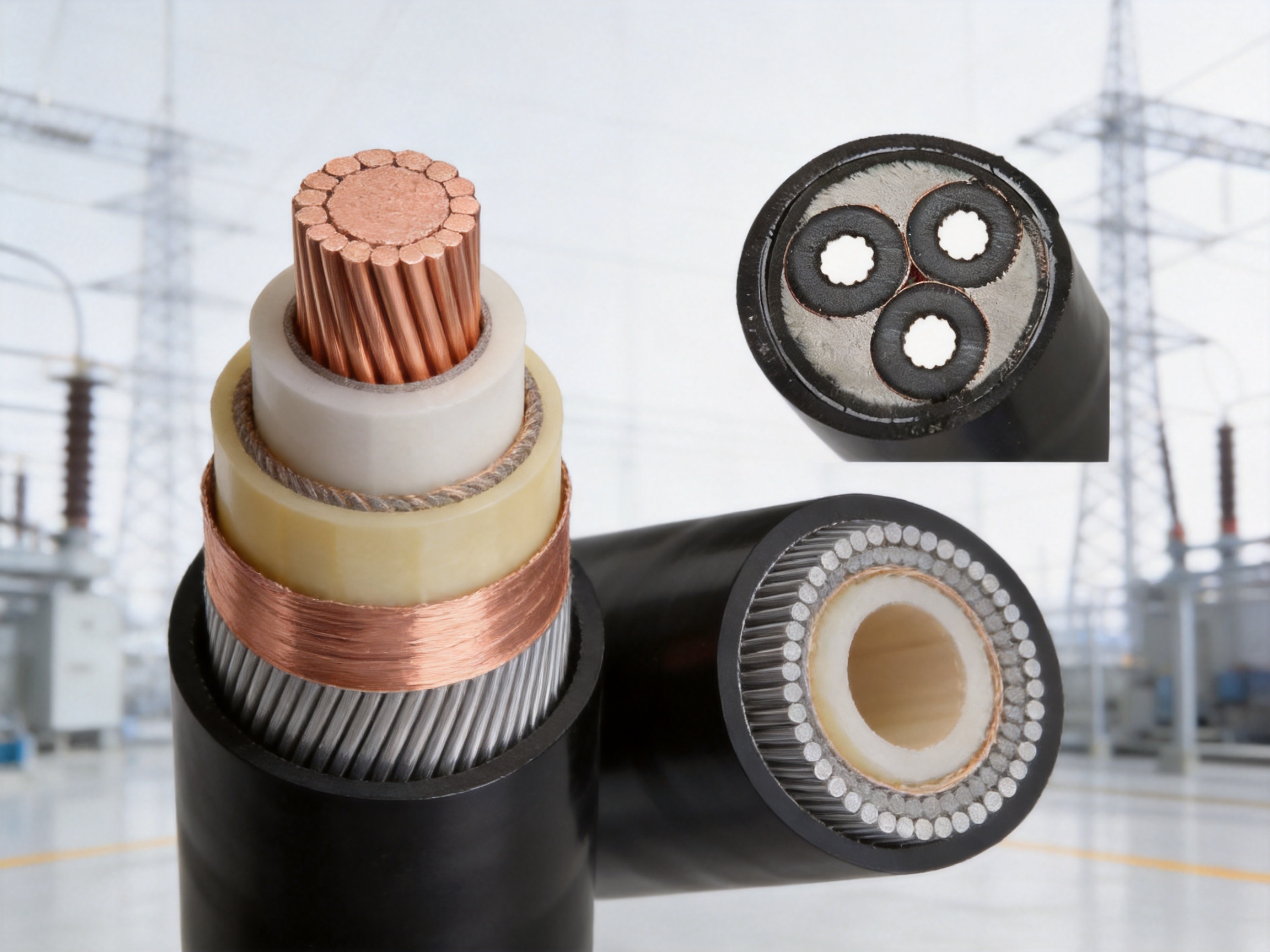
A high-performance armored cable depends on more than the specification of its raw materials. Conductor quality, dimensional accuracy, insulation cleanliness, extrusion stability, shield application, armor tension, sheath integrity, and final testing all influence field reliability. Anhui Zhishang Cable Technology Co., Ltd. integrates research and development, production, quality management, and sales within one organization, allowing the product to be developed and manufactured through a coordinated process.
Production begins with copper conductor preparation. Copper rods or suitable conductor materials are processed through drawing, stranding, compacting, and shaping operations according to the selected cross-section. Process control is important for maintaining conductor resistance, surface quality, flexibility, roundness, and dimensional consistency.
For larger cross-sections, compacting can improve the conductor’s geometric efficiency and help control the final cable diameter. For multi-core configurations, sector-shaped conductors can contribute to a more compact assembly. Each conductor design must remain compatible with the required bending performance, termination method, current rating, and short-circuit requirements.
XLPE insulation is applied through controlled extrusion. The extrusion process must maintain stable temperature, pressure, line speed, and material flow. Cleanliness is especially important in medium-voltage cable production because foreign particles, moisture, voids, and surface defects can create concentrated electrical stress.
Automated production lines help reduce variation between cable lengths and support repeatable process parameters. Dimensional checks can verify insulation thickness and concentricity, while electrical testing can identify defects that are not visible during visual inspection. Maintaining a stable production environment and applying documented process controls support consistent insulation performance.
After insulation, the cable receives its shielding structure. The wrapped copper tape must be applied with suitable overlap, tension, and continuity. In multi-core cable designs, the insulated cores are assembled with appropriate fillers, binders, or separation elements to achieve the required geometry and stability.
The assembly process influences cable roundness, flexibility, bending behavior, and the performance of subsequent armor and sheath layers. A poorly formed core assembly can create uneven pressure during armoring or produce localized stress when the cable is bent. Careful control at this stage therefore supports both electrical and mechanical reliability.
Fine round steel wire armor is applied around the cable assembly under controlled tension. The wires must be distributed evenly and maintained at a consistent lay angle. Excessive tension may deform the underlying sheath or core assembly, while insufficient tension may create loose armor, irregular diameter, or poor mechanical support.
Manufacturing controls should include inspection of wire quality, armor coverage, wire spacing, lay consistency, surface condition, and dimensional uniformity. The armor must remain stable during subsequent sheathing and during normal cable handling. The final design should also maintain the specified minimum bending radius without creating damaging concentrations of force.
The inner and outer sheaths are applied by extrusion using the specified PVC, polyethylene, or LSZH compound. Sheath extrusion must provide continuous coverage, appropriate thickness, strong adhesion or dimensional stability where required, and resistance to environmental exposure.
For LSZH designs, the compound formulation and processing conditions require particular attention because flame-retardant and low-smoke materials may have different extrusion behavior from conventional PVC. The selected sheath must meet the project’s requirements for flame retardancy, smoke emission, halogen content, weather resistance, oil resistance, and mechanical strength.
Testing is an essential part of quality assurance. Depending on the cable design, production order, and applicable standard, testing may include conductor resistance measurement, insulation resistance measurement, voltage withstand testing, dimensional inspection, sheath inspection, mechanical testing, flame-retardancy evaluation, and checks on armor continuity or construction.
The manufacturer provides product test reports for standard cable models and supports quality assurance through full-core and full-length pure copper specifications. Test documentation can help customers verify conformity, maintain project records, and support incoming inspection. For critical infrastructure, customers may also request witness testing, additional type testing, inspection plans, or customized documentation requirements.
Production capacity is valuable only when it is supported by process discipline and technical competence. The manufacturer’s approximately 5,000-square-meter production base, ten automated production lines, and reported monthly capacity of up to ten million meters provide a foundation for handling both routine and project-based demand. This can be particularly useful when a project requires multiple cable types, phased deliveries, or urgent replenishment of standard products.
A team of more than fifty employees includes quality engineers and research and development technicians with more than ten years of industry experience. Experienced technical personnel can help interpret drawings, review cable structures, select insulation and sheath materials, evaluate voltage levels, and identify installation constraints before production begins.
The company’s OEM/ODM capability is another competitive advantage. Customers may provide a cable drawing, technical specification, sample, equipment requirement, or project schedule. The engineering team can then work toward a customized construction involving conductor size, core count, voltage rating, shielding, armor, sheath material, color, packaging, labeling, and testing documentation.
Standard products are reported to be stocked for fast shipment, while customized products generally require seven to twenty days of lead time. Actual delivery depends on cable size, material availability, order quantity, testing requirements, packaging, and shipping arrangements. The combination of standard inventory and customization support gives project purchasers more flexibility than a supplier focused only on one production model.
An unarmored XLPE cable may be lighter, easier to bend, and less expensive. It can be a good choice in protected indoor routes, cable trays, conduits, or installations where mechanical loads are minimal. However, it provides less resistance to impact, compression, rodents, and longitudinal tension. The YJV32 cable is preferable when mechanical protection and tensile support are important design requirements.
Aluminum conductors can reduce cable weight and material cost, especially in large cross-sections. Copper conductors, however, offer higher conductivity and may allow a smaller conductor area for an equivalent current requirement. Copper also provides familiar termination characteristics and strong compatibility with many industrial accessories. The most economical selection depends on conductor size, route length, installation labor, accessory cost, current demand, and long-term energy losses.
Steel tape armor can provide useful radial protection and may be appropriate for direct-buried or fixed routes. Fine steel wire armor generally offers stronger tensile capability and is more suitable where the cable experiences longitudinal pulling or suspension forces. The trade-off is increased weight, cost, and installation complexity. The YJV32 design is therefore a more targeted solution for tension-critical routes rather than a universal replacement for every armored cable.
XLPE insulation provides a higher continuous operating temperature and strong dielectric performance compared with many lower-temperature thermoplastic alternatives. This can support greater current-carrying capability under comparable conditions and improve long-term thermal stability. The final advantage depends on conductor size, installation conditions, ambient temperature, grouping, and the precise insulation system.
PVC remains useful in many power applications, particularly where cost, flexibility, and general-purpose performance are priorities. However, XLPE generally offers better thermal performance and lower dielectric loss for medium-voltage and higher-demand distribution. The YJV32 design combines XLPE insulation with PVC or LSZH outer protection, providing a balanced system that uses each material where it offers the greatest practical value.
Installation quality has a direct effect on cable service life. Before delivery, project teams should confirm cable length, voltage rating, conductor cross-section, number of cores, sheath material, armor construction, drum dimensions, route geometry, and accessory compatibility. Cable drums should be stored upright on firm ground and protected from impact, water accumulation, contamination, and uncontrolled rolling.
The cable should be pulled using equipment suitable for its weight and construction. Where the cable is armored, pulling grips and accessories should engage the appropriate load-bearing components rather than placing excessive force on the outer sheath. Pulling tension should remain within the manufacturer’s approved limit, and sidewall pressure should be controlled at bends and rollers.
The minimum bending radius for the specified multi-core design is 15 times the cable outer diameter. This value should be respected during pulling, positioning, termination, and final fixing. Tight bends can deform the armor, damage the sheath, disturb the shield, or place stress on the insulation. Temporary bending during installation should not be treated as harmless simply because the cable later returns to a straighter route.
Installation should be performed at temperatures of 0°C or above unless a specific low-temperature procedure has been approved. Cold polymer materials can become less flexible, increasing the risk of sheath cracking or installation damage. If cable storage or transport occurs in cold conditions, the cable should be allowed to reach a suitable temperature before handling.
Vertical and suspended installations require dedicated clamps or fittings. The support system should distribute the cable load without crushing the sheath or cutting into the armor. Supports should be aligned with the route and spaced according to cable weight, vibration, structural movement, and engineering calculations. The cable should not be suspended from a connection point that was designed only for electrical termination.
At joints and terminations, the copper tape shield must be prepared and bonded according to the accessory manufacturer’s instructions. Shield continuity, grounding, stress control, sealing, and creepage distance are all important. Terminations should be selected for the exact voltage class, conductor shape, insulation diameter, shield construction, and environmental conditions.
After installation, inspection may include visual examination, sheath integrity testing, insulation resistance measurement, conductor continuity checks, shield bonding verification, and voltage withstand testing where required. Test procedures must be selected by qualified electrical personnel because inappropriate testing can damage equipment or create unsafe conditions.
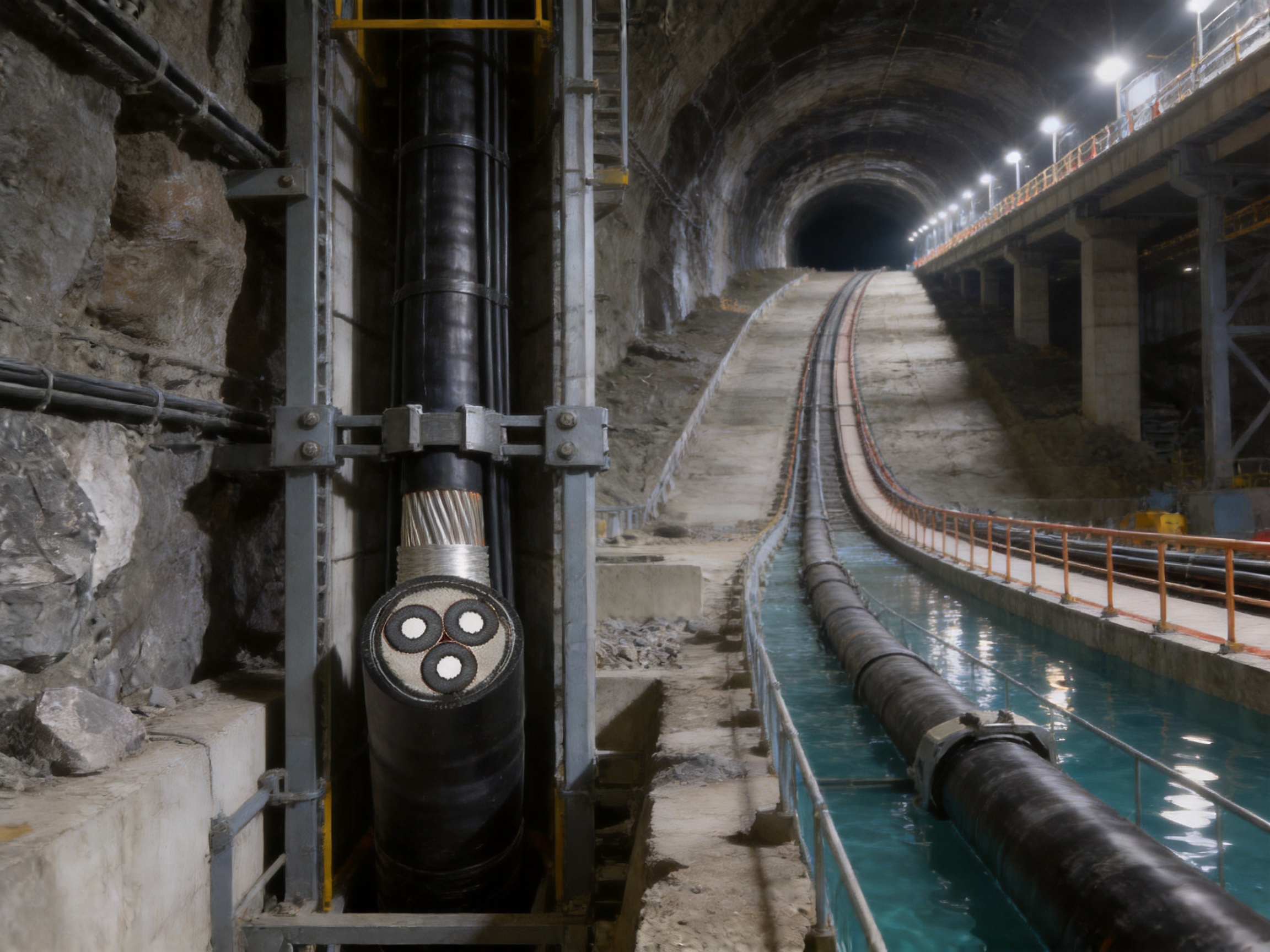
Choosing the correct YJV32 cable requires more than matching the nominal voltage and conductor area. The project team should evaluate the following factors:
First, determine the maximum continuous load current and expected load profile. Continuous, intermittent, emergency, and cyclic loads may require different thermal calculations. Ambient temperature, soil thermal resistivity, tray arrangement, grouping, and ventilation will influence allowable ampacity.
Second, calculate voltage drop over the complete route. This is especially important for long-distance feeders, motor circuits, mine systems, and equipment with strict undervoltage limits. Copper conductivity can help reduce voltage drop, but conductor cross-section must still be selected using the actual route length and load characteristics.
Third, evaluate short-circuit current and clearing time. The conductor, copper tape shield, grounding system, and protective devices must be coordinated so that the cable can withstand the thermal and electromagnetic effects of a fault until the protection system operates.
Fourth, analyze the route mechanically. Identify vertical height, slope, bend locations, pulling distance, support points, vibration sources, possible impact, burial depth, water exposure, and access for maintenance. This assessment determines whether YJV32 armor provides the required protection and what suspension or fixing accessories must be specified.
Fifth, select the outer sheath material according to the environment. PVC may be appropriate for many general outdoor and industrial applications. LSZH may be preferred in enclosed spaces where smoke and halogen emissions are restricted. The decision should also consider ultraviolet exposure, oil, chemicals, fire regulations, water, and temperature.
Finally, confirm documentation and delivery requirements. Critical projects may need material certificates, routine test reports, type-test evidence, inspection plans, certificates of conformity, drum schedules, cable identification, and special packaging. These requirements should be agreed before manufacturing begins.
Cable sustainability is not limited to the material used in the insulation or sheath. A cable that operates efficiently, avoids premature failure, and remains serviceable for many years can reduce replacement waste, emergency maintenance, and operational disruption. The low resistance of copper conductors supports energy efficiency, while the mechanical protection provided by steel wire armor can reduce the likelihood of damage-related replacement.
XLPE insulation contributes to long-term thermal stability, and the availability of LSZH sheath compounds can support projects with more demanding environmental and fire-safety objectives. Manufacturing efficiency is also relevant. Automated production lines, quality control systems, standardized processes, and planned material use can improve consistency and reduce avoidable production waste.
Lifecycle value should be evaluated through total cost rather than purchase price alone. A lighter unarmored cable may cost less initially, but it may require conduit, additional protection, or more frequent repairs. An armored cable may cost more and require heavier handling equipment, yet provide lower risk in an exposed or tension-bearing route. The correct comparison should include installation, accessories, testing, maintenance, downtime, and expected service life.
Power infrastructure rarely follows one universal cable configuration. Customers may require a particular conductor area, core arrangement, insulation level, shield design, armor size, sheath compound, flame-retardant grade, color, marking, packaging format, or delivery length. A manufacturer with OEM/ODM capability can adjust the cable construction to meet these requirements rather than forcing the project into an unsuitable standard product.
Customization may begin with a drawing, a sample, a written specification, or a description of the installation environment. The engineering team can review the electrical and mechanical requirements, identify potential conflicts, recommend a suitable layer structure, and prepare production documentation. This process is especially useful for equipment manufacturers, system integrators, infrastructure contractors, and distributors serving specialized markets.
Customized products generally require additional lead time for engineering review, material preparation, production scheduling, testing, and approval. The reported typical lead time is seven to twenty days, although actual timing depends on the complexity and quantity of the order. Early technical communication helps prevent delays and reduces the risk of changes after production has started.
YJV32 generally refers to a power cable using XLPE insulation, a PVC-related sheath designation, and fine steel wire armor. The exact construction can vary according to voltage level, number of cores, sheath materials, shielding arrangement, and applicable standard. The full technical specification should be reviewed before ordering.
It is available in several rated voltage configurations, including 3.6/6 kV, 6/10 kV, 8.7/15 kV, and 12/20 kV, in addition to lower-voltage options. Suitability depends on the system voltage, insulation coordination, accessories, grounding method, and applicable engineering standard.
The main advantage is improved mechanical protection and tensile capability. The armor helps resist pulling forces, compression, impact, abrasion, and rodent damage. It is particularly useful in vertical, sloping, suspended, underground, mining, pipeline, and other exposed routes.
No. The cable should be installed with dedicated clamps, suspension fittings, or another engineered support system. The armor improves tensile strength, but the complete installation must transfer cable weight safely to the supporting structure without damaging the sheath or armor.
The specified long-term operating temperature is up to 90°C at the conductor. Actual allowable current depends on ambient conditions, installation method, grouping, thermal resistance, and project standards.
The stated short-circuit temperature is up to 250°C for a maximum duration of five seconds. The protection system must clear faults within the approved time, and the conductor and shield must be properly coordinated with the calculated fault current.
For the specified multi-core construction, the minimum bending radius is 15 times the cable outer diameter. The project should confirm the exact value for the selected cable design and follow the manufacturer’s installation instructions.
Yes. The stated outer sheath options include PVC and low-smoke zero-halogen flame-retardant polyolefin. LSZH should be selected when smoke, halogen, or fire-performance requirements make it appropriate for the installation environment.
The stated cross-section range is 1.5 mm² to 800 mm². Availability of a specific conductor area depends on voltage rating, core arrangement, construction, production schedule, and order quantity.
The YJV32 cable provides substantially stronger mechanical protection and improved resistance to tensile loading, impact, compression, and rodents. An unarmored cable may be lighter and easier to bend, so it can remain preferable for protected routes where mechanical hazards are low.
Yes. OEM/ODM support is available based on customer drawings, samples, or defined project requirements. Customization may include conductor structure, voltage class, core arrangement, shielding, armor, sheath, flame-retardant grade, color, marking, packaging, and testing documentation.
Customers should confirm voltage rating, conductor material and cross-section, number of cores, insulation, shield, armor, inner and outer sheath materials, flame-retardant requirements, route environment, cable length, drum size, test requirements, delivery schedule, and applicable standards. Installation tension and support requirements should also be reviewed for vertical or suspended routes.
The YJV32 high-conductivity high-voltage cable is a specialized solution for power systems that require both dependable electrical transmission and strong mechanical protection. Its copper conductor supports efficient power delivery, while XLPE insulation provides stable dielectric and thermal performance. The wrapped copper tape shield contributes to electric-field control and grounding functionality, and the fine round steel wire armor improves tensile strength, impact resistance, compression resistance, and protection against external damage.
This combination makes the cable particularly suitable for vertical shafts, steep slopes, bridge suspensions, underwater routes, mine hoisting systems, pipelines, tunnels, outdoor distribution, and long-distance industrial feeders. Its broad range of voltage options and conductor cross-sections enables project engineers to select a construction suited to different power requirements.
The product’s value is reinforced by the manufacturer’s integrated R&D, production, testing, customization, and supply capabilities. Modern production facilities, automated lines, experienced technical personnel, standard product inventory, OEM/ODM support, and documented quality assurance provide a practical foundation for both standard procurement and specialized project development.
For the best result, the cable should be specified as part of a complete electrical and mechanical system. Correct conductor sizing, voltage selection, shield bonding, support design, bending control, termination, testing, and maintenance planning are essential. When these factors are properly coordinated, YJV32 cable can provide a durable and efficient power transmission solution for demanding fixed installations.
GB/T 12706.1, Power Cables with Extruded Insulation and Their Accessories for Rated Voltages from 1 kV to 35 kV, applicable construction and dimensional requirements.
GB/T 19666, General Rules for Flame Retardant and Fire Resistant Electric Wires and Cables, applicable flame-retardant classifications.
International Electrotechnical Commission, relevant standards for power cables with extruded insulation, electrical testing, conductor properties, and installation practices.
Technical product information for YJV32 copper-conductor XLPE-insulated fine steel wire armored power cable.
Manufacturer-provided information regarding production facilities, quality assurance, OEM/ODM support, standard product supply, and cable customization.

We firmly believe that good cables are not only a competition of materials, but also a reflection of craftsmanship, quality, and responsibility.

Links
Product
Send Inquiry
No. 29 Sankeshu Road, Xuanzhou District, Xuancheng City, Anhui Province, China
+86-18621104555/+86-563-2622999
 Electrical Cable Manufacturer
OEM/ODM Wire and Cable Solutions
 English
 Español
 عربى
 русский