
Get more content that can help you
Content
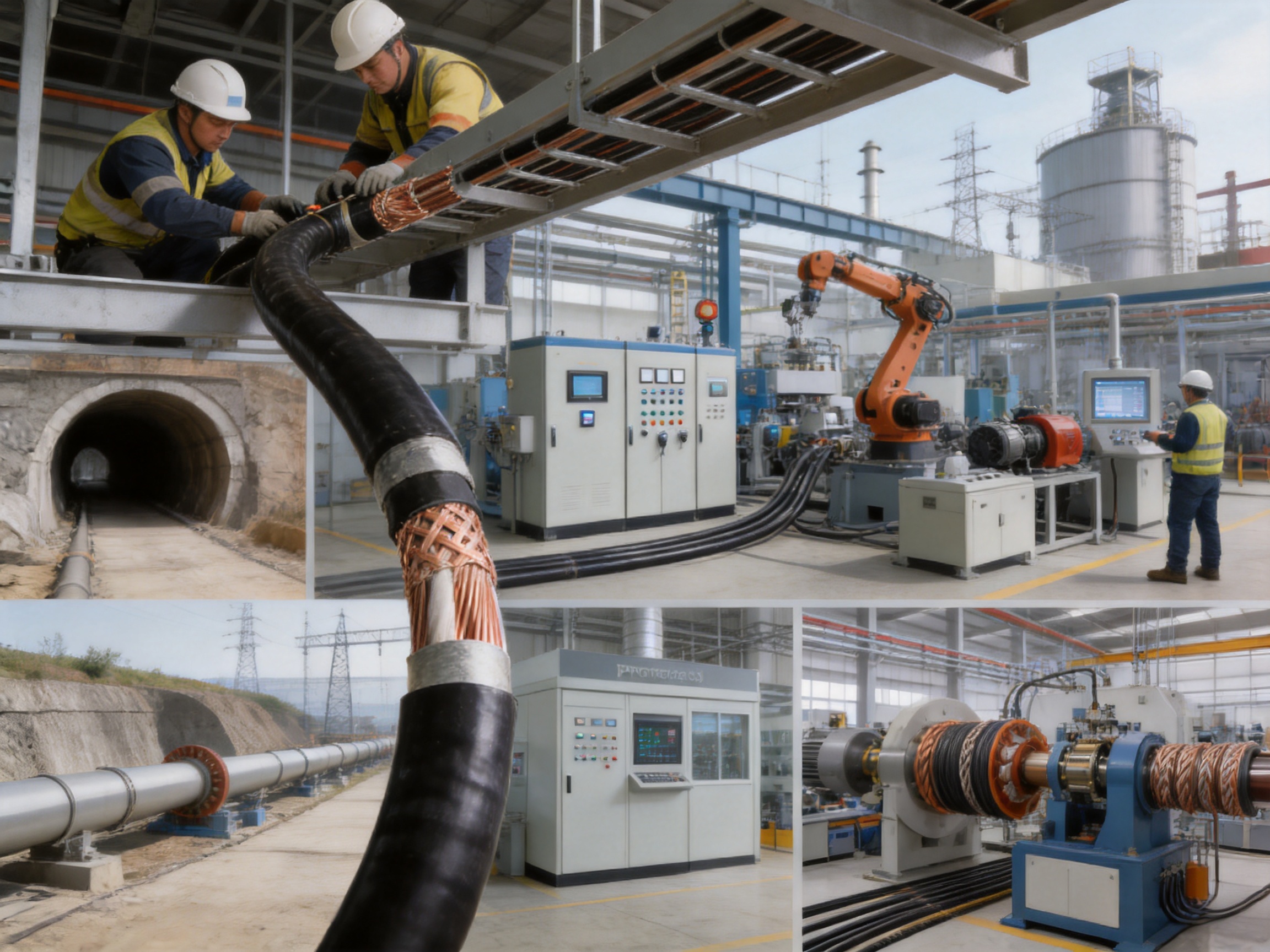
Modern industrial systems increasingly depend on accurate, uninterrupted communication between sensors, programmable logic controllers, distributed control systems, monitoring equipment, computers, and field devices. In these environments, a communication cable is not simply a passive connection. It is an essential part of the signal chain, and its construction directly affects data accuracy, system availability, maintenance costs, and operational safety.
The DJYVP3-22 electronic computer cable is designed for applications that demand more than ordinary instrumentation or communication wiring can provide. It combines twisted-pair conductors, individual pair shielding, overall shielding, and double-layer galvanized steel tape armor in one integrated cable structure. This combination gives the cable strong resistance to electromagnetic interference, mechanical damage, moisture, abrasion, compression, and challenging installation conditions.
With a rated voltage of 300/500V, a characteristic impedance of 100 Ω ±6 Ω, a broad pair-count range, and conductor cross-sections from 1.0 mm² to 10.0 mm², the cable can be adapted to many industrial communication and control applications. It is suitable for direct burial, conduit installation, tunnels, pipelines, industrial automation systems, high-electromagnetic-interference zones, and other locations where signal integrity and physical protection are equally important.
This article examines the construction, electrical performance, shielding system, armor design, installation compatibility, manufacturing capabilities, quality controls, applications, selection considerations, and competitive advantages of the DJYVP3-22 cable.
Industrial communication networks operate in environments that are considerably harsher than office or residential installations. Motors, variable-frequency drives, transformers, welding equipment, switching systems, relays, generators, and high-current power cables can all produce electromagnetic fields. These fields may couple into nearby signal cables and create unwanted noise, data errors, control instability, or false readings.
Mechanical conditions can be equally demanding. Cables installed in factories, tunnels, underground ducts, military facilities, power plants, and process plants may be exposed to compression, impact, vibration, pulling forces, abrasion, moisture, rodents, and accidental contact with tools or construction equipment. A cable that provides excellent electrical performance but insufficient mechanical protection may not deliver reliable service over its intended operating life.
Electronic computer cable is used to connect and transmit low-level signals between computers, control equipment, instrumentation systems, and communication devices. Its design generally emphasizes controlled impedance, balanced twisted pairs, low capacitance, stable insulation resistance, and shielding against electrical interference.
The DJYVP3-22 configuration extends these features by adding multiple shielding layers and double-layer steel tape armor. This makes it especially useful where ordinary unshielded, lightly shielded, or non-armored cables would be vulnerable.
The DJYVP3-22 cable is built as a multi-layer protection system. Each layer performs a specific function, and the layers work together to protect signal transmission from both electrical and physical threats.
The primary conductive element is an annealed copper conductor, available in solid or stranded construction. Copper provides high conductivity, stable termination performance, and good compatibility with common industrial connectors and terminal systems.
The conductors are arranged into twisted pairs. Twisting reduces the area exposed to external electromagnetic fields and helps the two conductors experience similar interference levels. When the receiving equipment detects the voltage difference between the conductors, common-mode interference can be substantially reduced.
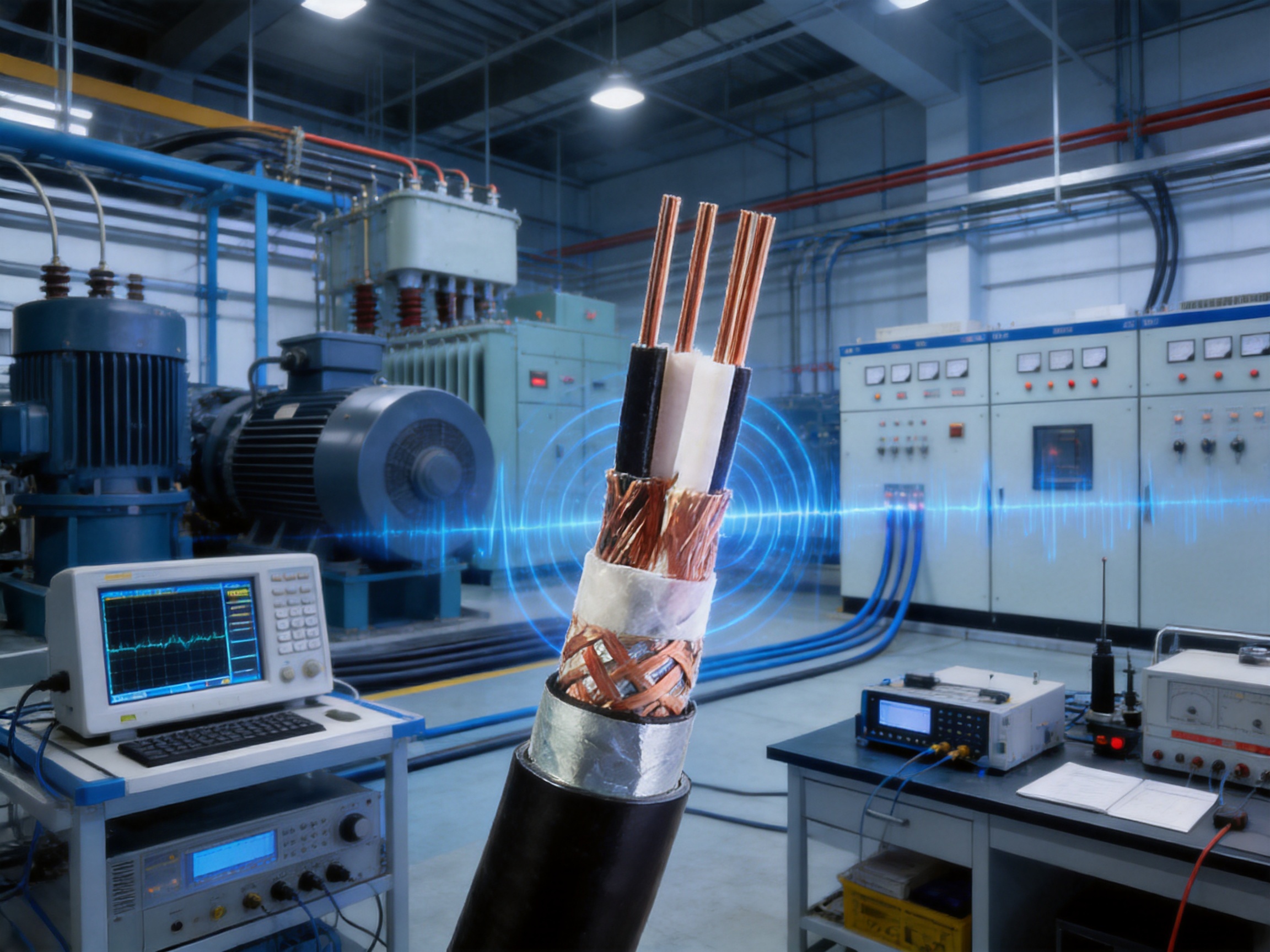
Each pair is protected by an aluminum foil shield and a tinned copper drain wire. A copper braid provides an additional overall shielding layer, while an aluminum-polyester composite tape contributes another layer of electromagnetic protection. The completed cable also includes double-layer galvanized steel tape armor beneath the outer sheath.
This arrangement is more comprehensive than a basic pair-shielded cable. It addresses interference at the pair level, the overall cable level, and the physical protection level. The result is a cable designed for signal circuits located close to powerful electrical equipment or routed through exposed industrial areas.
The cable uses solid or stranded annealed copper conductors. Solid conductors can provide consistent electrical characteristics and are often selected for fixed installations with limited movement. Stranded conductors offer improved flexibility and can be more convenient when routing the cable through bends, cabinets, conduits, and equipment connection areas.
The specified cross-section range is 1.0 mm² to 10.0 mm². This range allows users to balance current-carrying capability, mechanical strength, voltage drop, flexibility, and termination requirements according to the application.
Using copper conductors also supports reliable connections. Properly prepared copper conductors can be terminated with standard industrial lugs, terminals, and connection hardware. The conductor selection should nevertheless be matched to the project’s current, distance, installation method, temperature, and applicable electrical standards.
The cable is available from 1 pair to 24 pairs. The twisted-pair structure is important for communication and instrumentation circuits because it improves balance between the two signal conductors and helps reduce crosstalk.
Crosstalk occurs when a signal from one circuit unintentionally couples into a neighboring circuit. In multi-pair cables, careful pair twisting, consistent geometry, and appropriate insulation thickness help reduce this effect. The final performance depends not only on the cable but also on termination quality, grounding, installation separation, and the characteristics of the connected equipment.
For high-density control systems, a multi-pair configuration can reduce the number of individual cables required. This can simplify cable routing, tray organization, cabinet entry, and maintenance documentation. The correct pair count should be selected based on the number of circuits, spare capacity requirements, redundancy strategy, and future expansion plans.
The conductors are insulated with polyethylene, commonly known as PE. Polyethylene is widely used in communication and signal cables because it provides favorable dielectric properties, stable insulation resistance, and comparatively low signal loss.
The specified insulation thickness ranges from 0.5 mm to 1.2 mm. The final thickness depends on conductor size, voltage requirements, cable design, and the intended electrical performance.
High insulation resistance is important for maintaining signal stability and reducing leakage between conductors. The stated insulation resistance is at least 10,000 MΩ·km, indicating a high level of insulation performance under the specified test conditions.
Each twisted pair includes an aluminum foil shield and a tinned copper drain wire. Pair-level shielding helps prevent interference generated by one pair from coupling into adjacent pairs. It also protects sensitive pair circuits from external electromagnetic fields before interference reaches the conductors.
The drain wire provides a practical electrical path for connecting the shield to a grounding or bonding system. Proper shield termination is essential. An improperly connected shield can reduce the effectiveness of the cable and may create undesirable grounding conditions.
Pair shielding is particularly valuable when different types of signals share the same cable. For example, analog measurement signals, low-level control signals, pulse signals, and communication circuits may have different susceptibility to interference. Individual pair shielding adds separation between these circuits.
The cable includes copper braid shielding and an aluminum-polyester composite tape overall shield. These layers surround the cable assembly and provide broad protection against electromagnetic interference from outside the cable.
The aluminum-polyester tape offers continuous foil coverage, while the copper braid contributes mechanical strength, flexibility, and conductive coverage. The combination can provide more comprehensive shielding than a single layer alone.
Overall shielding is especially valuable in industrial facilities containing motor control centers, frequency converters, high-current busbars, welding equipment, power electronics, and switching devices. It can also help reduce the electromagnetic emissions produced by the cable itself, depending on circuit design and grounding practice.
The armored structure consists of double-layer galvanized steel tape wrapped around the cable. This armor is designed to improve resistance to compression, impact, abrasion, and rodent damage.
Double-layer armor offers a higher level of mechanical protection than a non-armored cable. It can help protect the insulated cores and shielding layers during transport, installation, backfilling, and service. The galvanized surface also supports corrosion resistance in environments where the armor may be exposed to humidity or incidental moisture.
Armor does not eliminate the need for correct installation. The cable should still be handled according to its bending radius, pulling tension, temperature limits, and approved installation method. Armor continuity and grounding should also be considered in the system design.
The filling material is non-hygroscopic polypropylene yarn. Its purpose is to help maintain the internal cable structure while limiting moisture absorption. A stable internal assembly can help preserve the relative position of pairs, shields, and armor during manufacturing and installation.
The inner sheath is made from polyvinyl chloride and has a specified thickness of 1.2 mm to 1.8 mm. It provides an additional protective layer between the internal assembly and the armor.
The outer sheath is available in PVC or low-smoke zero-halogen material. PVC is widely used because it offers a practical balance of flexibility, mechanical strength, weather resistance, and cost. LSZH is suitable for projects where smoke generation and halogen emissions must be limited during a fire.
The outer sheath thickness ranges from 2.5 mm to 3.5 mm. The final thickness is determined by the cable size and design configuration.
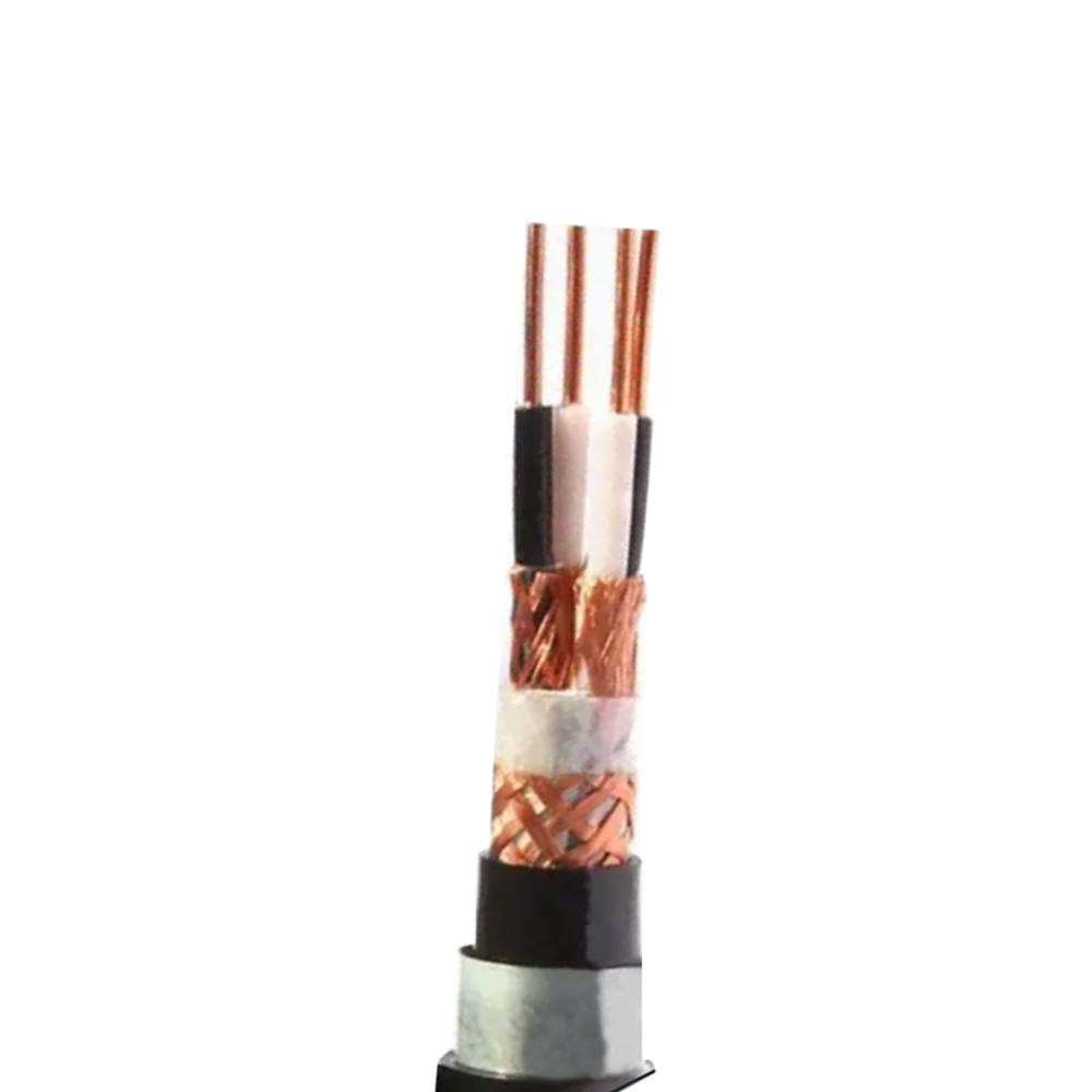
DJYVP3-22 Strong installation compatibility Electronic Computer Cable
The following table summarizes the principal technical parameters provided for the DJYVP3-22 electronic computer cable.
| Parameter | Specification |
|---|---|
| Conductor | Solid or stranded annealed copper conductor |
| Cross-section range | 1.0 mm² to 10.0 mm² |
| Number of pairs | 1 pair to 24 pairs |
| Rated voltage | 300/500 V |
| Test voltage | 3 kV AC for 1 minute |
| Insulation material | Polyethylene |
| Insulation thickness | 0.5 mm to 1.2 mm |
| Pair shielding | Aluminum foil with tinned copper drain wire |
| Overall shielding | Copper braid and aluminum-polyester composite tape |
| Armor | Double-layer galvanized steel tape |
| Filling material | Non-hygroscopic polypropylene yarn |
| Inner sheath | PVC |
| Outer sheath | PVC or LSZH |
| Capacitance unbalance | ≤ 50 pF/100 m at 1 kHz |
| Characteristic impedance | 100 Ω ±6 Ω |
| Working capacitance | ≤ 52 nF/km |
| Attenuation | ≤ 1.0 dB/100 m at 1 MHz |
| Insulation resistance | ≥ 10,000 MΩ·km |
The cable has a characteristic impedance of 100 Ω ±6 Ω. Controlled impedance is important in communication systems because impedance mismatches can cause signal reflection. Reflections may reduce signal quality, distort waveforms, and limit the effective transmission distance or data rate.
A nominal 100-ohm design is widely associated with balanced communication and data transmission systems. The actual system performance depends on the complete transmission channel, including cable length, connectors, terminal equipment, patching components, and termination practices.
Maintaining cable geometry during manufacturing is essential to impedance control. Conductor spacing, insulation dimensions, pair twisting, shielding placement, and sheath pressure can all influence the final impedance. Consistent production processes help keep these variables within the required range.
The stated working capacitance is no more than 52 nF/km, while capacitance unbalance is limited to 50 pF/100 m at 1 kHz. These characteristics are important for balanced signal circuits, especially when multiple pairs share one cable.
Excessive capacitance can load the connected equipment and reduce the strength or speed of transmitted signals. Capacitance imbalance can create differences between the two conductors of a pair, increasing susceptibility to common-mode interference and reducing balance performance.
The twisted-pair layout, insulation consistency, conductor positioning, and shielding design all influence capacitance. Careful control of these features supports stable electrical characteristics throughout the cable length.
The specified attenuation is no more than 1.0 dB/100 m at 1 MHz. Attenuation represents the reduction in signal strength as the signal travels through the cable. Lower attenuation generally supports better signal margins and more reliable communication.
Attenuation is affected by conductor resistance, dielectric losses, cable geometry, frequency, temperature, and installation conditions. The stated value provides an important reference for system designers, but the maximum allowable cable length should be determined according to the communication protocol and complete network design.
A minimum insulation resistance of 10,000 MΩ·km indicates strong insulation performance. High insulation resistance helps limit leakage currents and unwanted interactions between circuits.
The cable is tested at 3 kV AC for one minute. This test verifies the dielectric strength of the insulation system under the specified test condition. Routine testing and final inspection help identify manufacturing defects before the product is delivered.
Electrical testing should be complemented by visual inspection, dimensional checks, conductor resistance testing, shield continuity testing, and armor continuity verification where applicable.
Many standard control or computer cables use one overall shield or a simple foil shield around a group of conductors. That design may be sufficient in a relatively quiet electrical environment, but it may not provide enough protection near high-power equipment.
The DJYVP3-22 uses pair shielding together with multiple overall shielding elements. This layered structure provides protection at several levels. It helps isolate individual pairs, limits coupling between pairs, and reduces the effect of external electromagnetic fields.
For facilities with strong interference, this design can offer a significant advantage over lightly shielded cables. It may reduce signal errors, nuisance alarms, unstable readings, and communication interruptions when installed and grounded correctly.
Non-armored cables are lighter and may be easier to handle, but they can be more vulnerable to compression, sharp objects, rodents, accidental impact, and underground installation hazards. The double-layer steel tape armor of the DJYVP3-22 provides a stronger physical barrier.
This is particularly useful in direct-burial applications, tunnels, pipelines, industrial floors, cable trenches, and exposed routes where the cable may encounter mechanical stress. The armored design can reduce the risk that a local impact will damage the internal conductors or shields.
The cable can be considered for direct burial or conduit installation, depending on the project’s engineering requirements and applicable regulations. Its integrated armor and protective sheath may reduce the need for additional mechanical protection in some installations.
It can also be routed through industrial cable trays, equipment areas, tunnels, and control-system infrastructure. This flexibility may reduce the number of specialized cable types required for a project.
Installation compatibility should not be confused with universal suitability. The project designer must still verify bending radius, cable weight, pulling tension, fire performance, grounding, environmental temperature, and local code requirements.
The combination of PE insulation, PVC or LSZH sheathing, non-hygroscopic filler, multiple shields, and double-layer armor gives the cable a strong environmental profile. It is intended for situations where moisture, wear, interference, and mechanical stress may occur together.
Using a cable designed for the actual environment can improve lifecycle reliability. Fewer cable failures mean less troubleshooting, reduced production interruption, and lower maintenance labor. In critical infrastructure, the cost of a communication failure can exceed the original cable purchase price many times over.
The availability of an LSZH outer sheath is an important advantage for projects with strict fire-safety requirements. During a fire, low-smoke zero-halogen materials are designed to produce reduced smoke and limited halogen-containing emissions compared with conventional halogenated materials.
LSZH construction may be preferred in enclosed public facilities, transportation infrastructure, control rooms, tunnels, high-occupancy buildings, and other locations where smoke visibility and corrosive gas exposure are major concerns.
The required fire performance should always be verified against the applicable project specification. An LSZH option does not automatically mean that the cable meets every flame-retardance, fire-resistance, or circuit-integrity classification.
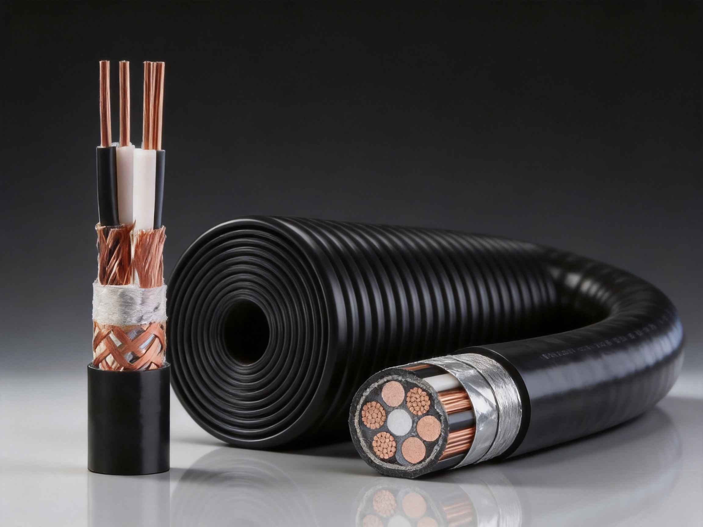
Energy facilities typically contain high-power electrical equipment, extensive control systems, and strict requirements for operational continuity. Signal cables may run near generators, transformers, motors, switching devices, and power distribution equipment.
The DJYVP3-22 design can be considered for control, monitoring, instrumentation, and communication circuits where strong shielding and mechanical protection are required. In nuclear or other highly regulated facilities, the cable must be evaluated against project-specific qualification, fire, aging, radiation, seismic, and safety requirements before approval.
Military facilities and security systems may require protected signal transmission in electrically complex and physically demanding environments. The triple-shielded construction can help reduce electromagnetic interference, while the armored structure provides additional resistance to impact and accidental damage.
Potential uses include protected communication routes, monitoring systems, control equipment, perimeter systems, command infrastructure, and equipment shelters. Project-specific requirements for security, traceability, environmental qualification, and electromagnetic compatibility should be confirmed during procurement.
Industrial automation systems connect sensors, actuators, controllers, drives, computers, and supervisory systems. These systems often operate in areas where control cables share space with motor and power cables.
The twisted-pair structure supports balanced signal transmission, while multiple shields help protect low-level signals. The multi-pair configuration can also support numerous circuits within one organized cable route.
Typical uses may include process monitoring, programmable control systems, distributed input and output, equipment interconnection, production-line data systems, and factory automation networks.
Tunnels and underground installations may expose cables to moisture, abrasion, compression, construction activity, and limited maintenance access. The armored construction provides an additional layer of mechanical protection, and the LSZH option may be valuable where smoke and fire behavior are important.
Before installation, designers should review drainage, water exposure, cable support, ventilation, emergency access, grounding, and fire-safety requirements. Cable routing should also prevent unnecessary contact with sharp edges or high-temperature surfaces.
Pipeline and process facilities often include long cable routes, remote instruments, pumps, valves, control panels, and communication equipment. The cable may be installed outdoors, underground, in trays, or inside protective conduits.
The cable’s combination of shielding and armor can support reliable signal transmission over challenging routes. The exact sheath material should be selected according to exposure to oil, chemicals, ultraviolet radiation, temperature extremes, and other environmental factors.
Areas surrounding variable-frequency drives, large motors, induction equipment, welding systems, high-current conductors, and switching equipment can be challenging for signal cables. The triple-shielded design is intended for precisely these demanding conditions.
However, cable shielding is only one part of an electromagnetic compatibility strategy. Separation from power cables, appropriate grounding at the correct points, proper cabinet design, suitable connectors, and controlled routing are also essential.
The performance of a specialized armored computer cable depends on manufacturing consistency. A technically impressive design can fail to deliver its intended benefits if conductor dimensions, pair geometry, shield coverage, insulation thickness, or armor application vary excessively.
The manufacturer operates a production base of approximately 5,000 square meters with more than 10 automated production lines. This production structure supports repeatable manufacturing, process standardization, and the ability to handle both standard product orders and customized cable requirements.
Copper wire drawing reduces the conductor to the required diameter while improving dimensional consistency. The process must control surface quality, elongation, tensile strength, and electrical resistance.
Annealing follows the drawing process to restore flexibility and reduce internal stress. Properly annealed copper is better suited to bending, stripping, termination, and cable forming.
For stranded conductors, multiple fine wires are assembled according to the required construction. Stranding parameters influence flexibility, conductor roundness, resistance, and compatibility with the insulation process.
Polyethylene insulation is applied through controlled extrusion. The extrusion line must maintain stable temperature, pressure, line speed, and cooling conditions. Uneven insulation can affect electrical performance, conductor centering, capacitance, and dielectric strength.
Online diameter monitoring and spark testing can help identify irregularities. After extrusion, samples may be checked for thickness, concentricity, tensile properties, elongation, aging behavior, and insulation resistance.
After insulation, conductors are twisted into pairs. Twist length and pair geometry influence crosstalk, capacitance balance, impedance, and attenuation.
Consistent twisting is therefore a critical process. Excessive variation can produce inconsistent electrical characteristics along the cable. Automated equipment helps maintain stable production parameters and repeatability between batches.
Each pair receives its aluminum foil shield and tinned copper drain wire. The foil must be applied with appropriate overlap and continuity. The drain wire must remain in reliable contact with the conductive side of the shield.
Shield application requires careful control because gaps, wrinkles, poor overlap, or incorrect drain-wire placement can reduce shielding performance. Inspection may include visual review, dimensional measurement, and continuity testing.
Multiple pairs are assembled into the required core arrangement. Non-hygroscopic polypropylene yarn is used as a filler to support the core and maintain a stable circular form.
Correct assembly reduces excessive voids, prevents pair displacement, and supports consistent sheath application. The cable core must remain sufficiently stable during subsequent shielding, armoring, and sheathing operations.
The assembled core receives the overall shielding system, including copper braid and aluminum-polyester composite tape. Braid coverage, tape overlap, tension, and alignment are controlled to achieve consistent protection around the cable.
Manufacturing personnel must balance shielding coverage with flexibility and dimensional requirements. Excessive tension can distort the core, while insufficient tension may create loose or irregular layers.
The PVC inner sheath is extruded around the shielded core. It provides a smooth and stable surface for the application of the steel tape armor.
Double-layer galvanized steel tape is then wrapped around the inner sheath. Armor overlap and winding tension are important for mechanical performance. The armor must protect the cable without causing excessive deformation or restricting the intended bending characteristics.
The final PVC or LSZH outer sheath is extruded over the armored cable. This process provides environmental protection, a durable external surface, and a means of applying product identification markings.
Outer sheath quality may be evaluated through thickness measurement, surface inspection, spark testing where applicable, tensile and elongation tests, aging tests, and visual verification of marking clarity.
Quality assurance should cover raw materials, intermediate processes, final assembly, and finished-cable performance. A complete quality program helps reduce the risk that a small production variation will become a field failure.
Copper, polyethylene, PVC, LSZH compounds, aluminum foil, copper braid, drain wire, steel tape, and filler materials should be checked before entering production. Important checks may include supplier documentation, appearance, dimensions, mechanical properties, electrical properties, and batch identification.
Material traceability allows production teams to link finished cable to specific raw-material batches. This supports investigation, corrective action, and customer documentation.
During manufacturing, operators and quality personnel can monitor conductor diameter, insulation thickness, pair twist, shield placement, braid coverage, sheath thickness, armor overlap, cable diameter, and marking quality.
Automated production lines can support consistency, but process discipline remains essential. Equipment calibration, preventive maintenance, operator training, and documented work instructions all contribute to product reliability.
Electrical testing may include conductor resistance, insulation resistance, dielectric withstand, capacitance, capacitance unbalance, characteristic impedance, attenuation, shield continuity, and pair identification.
Testing at appropriate stages can identify defects earlier than final inspection alone. For example, an insulation issue can be detected after extrusion, while an overall shield problem can be identified before armoring.
Mechanical tests may evaluate tensile strength, elongation, bending behavior, sheath integrity, armor continuity, and resistance to impact or compression where required by the project.
Environmental tests depend on the selected construction and the customer’s specifications. They may include heat aging, cold bending, moisture exposure, ultraviolet resistance, oil resistance, chemical resistance, flame performance, and smoke testing.
Customers should request the relevant test reports and confirm that the tested configuration corresponds to the cable they intend to purchase.
Industrial projects often require cable designs that differ from standard catalog configurations. Requirements may include a specific conductor size, pair count, insulation thickness, shielding arrangement, sheath color, sheath material, marking format, packaging method, or delivery length.
The manufacturer supports OEM and ODM development based on customer drawings or samples. Technical engineers can assist with cable selection and design according to project requirements.
Customization may be useful when the installation has unusual space limits, special temperature conditions, strict fire-safety rules, a particular connector system, or a defined electrical interface. It can also help users standardize cable construction across multiple projects.
A well-defined customization process should begin with a technical specification. This document should identify conductor construction, cross-section, pair count, electrical parameters, shield termination, armor requirements, sheath material, operating temperature, installation method, applicable standards, inspection requirements, packaging, and delivery schedule.
Prototype or sample approval can reduce risk before large-scale production. Customers should review dimensions, flexibility, marking, termination compatibility, and test results before authorizing the full order.
Signal cables should be routed away from high-power cables whenever practical. Where crossing is unavoidable, a controlled crossing arrangement, often with an appropriate angle, may reduce parallel electromagnetic coupling.
Separate trays, partitions, conduits, and cable channels can improve electromagnetic compatibility. The route should also avoid excessive heat, sharp edges, standing water, chemical exposure, and locations where the cable may be crushed by equipment or vehicles.
Armored cables are mechanically strong but should not be bent beyond the manufacturer’s recommended minimum bending radius. Excessive bending can deform the armor, compress the insulation, disturb pair geometry, or damage the sheath.
During pulling, the installation team should control pulling tension and prevent twisting. Cable rollers, suitable pulling equipment, and adequate route preparation can reduce installation stress.
The effectiveness of a shield depends heavily on termination and grounding. Engineers should determine whether the shield is grounded at one end, both ends, or through a specific equipment bonding arrangement based on the signal type and system design.
In high-frequency or high-noise environments, a low-impedance bonding method may be preferable to a long pigtail. The installation should follow the equipment manufacturer’s grounding instructions and the applicable electrical standards.
Metal armor should be handled as part of the overall electrical and mechanical design. Armor continuity, bonding, grounding, termination kits, and gland selection should be specified before installation.
Improper armor termination can compromise safety, shielding performance, or water resistance. Qualified electrical personnel should complete the termination and verify continuity after installation.
After installation, the cable should be inspected for sheath damage, correct identification, proper routing, acceptable bend radius, and secure support. Electrical tests may include conductor continuity, insulation resistance, shield continuity, armor continuity, and communication performance.
Test results should be documented for commissioning and future maintenance. Clear records make it easier to identify whether a later fault is caused by the cable, a termination, connected equipment, or an environmental event.
The purchase price of a cable is only one part of its total cost. Installation labor, protective conduits, field repairs, equipment downtime, troubleshooting, replacement access, and production losses can have a greater financial impact than the initial material cost.
The DJYVP3-22 design may support lifecycle cost control in several ways. Its integrated armor can reduce the need for additional mechanical protection in suitable installations. Its multiple shielding layers can help reduce interference-related faults. Its multi-pair configuration can simplify routing and cable management. Its LSZH option can support compliance in fire-sensitive facilities.
Reliability is particularly valuable in remote or difficult-to-access areas. Replacing a cable in a tunnel, underground duct, power plant, or secured facility may require extensive preparation and operational interruption. Selecting a cable with appropriate environmental and mechanical protection at the design stage can reduce these risks.
Lifecycle value still depends on correct specification and installation. An over-protected cable used in a simple environment may be unnecessarily expensive, while an under-protected cable used in a harsh environment may create repeated failures. The best solution is the one matched to actual operating conditions.
Anhui Zhishang Cable Technology Co., Ltd. integrates cable research and development, production, and sales. Its operations are supported by a production base of approximately 5,000 square meters and more than 50 employees, including quality engineers and research and development technicians with more than 10 years of industry experience.
The company serves industrial automation, weak-current engineering, intelligent manufacturing, appliance equipment, power engineering, and related applications. Its stated business philosophy emphasizes quality orientation, integrity, and stability.
Its production organization includes more than 10 automated production lines and a reported monthly output of up to 10 million meters. This capacity can support standard product supply, project-based production, and customized cable development.
The company offers full-core and full-length pure-copper specifications for applicable products, product test reports, and warranty support for standard cable models. Standard products may be stocked for fast shipment, while customized products generally require a lead time of approximately 7 to 20 days, subject to the final design and order quantity.
The technical team provides selection guidance and tailor-made cable design solutions based on project requirements. This is important for industrial buyers who need more than a generic cable description. A supplier able to review drawings, samples, installation conditions, and electrical requirements can help reduce specification errors.
The company also emphasizes green manufacturing and responsible production practices. Its products are supplied to markets including the United States, Canada, Australia, Japan, and parts of Eurasia. International supply requires attention to documentation, packaging, product marking, quality consistency, and customer-specific standards.
Before ordering DJYVP3-22 cable, the buyer should confirm the following points:
1. Required number of twisted pairs, including spare pairs for future expansion.
2. Required conductor cross-section and whether solid or stranded conductors are preferred.
3. Communication protocol, maximum operating frequency, transmission distance, and impedance requirement.
4. Required rated voltage and test voltage.
5. Required shield configuration and preferred shield termination method.
6. Direct-burial, conduit, tray, tunnel, pipeline, or indoor installation method.
7. Required outer sheath material, including PVC or LSZH.
8. Temperature range, moisture exposure, ultraviolet exposure, oil exposure, chemical exposure, and mechanical hazards.
9. Fire, smoke, halogen, flame-retardance, or circuit-integrity requirements.
10. Minimum bending radius, pulling distance, cable drum dimensions, and installation access.
11. Required standards, inspection procedures, test reports, labeling, and traceability documents.
12. Delivery length, packaging, forecast demand, and whether standard stock or customized production is required.
Providing this information at the quotation stage enables the technical team to recommend a suitable configuration and avoid delays caused by incomplete specifications.
The designation identifies an electronic computer cable configuration with multiple shielding layers and steel tape armor. The product combines twisted pairs, individual pair shielding, overall shielding, and double-layer galvanized steel tape armor.
The stated range is from 1 pair to 24 pairs. The correct pair count should be selected according to the number of circuits, required spare capacity, and network expansion plan.
Its armored structure supports consideration for direct-burial installations and other mechanically demanding routes. The final suitability must be confirmed against soil conditions, moisture exposure, local regulations, burial depth, drainage, and project-specific requirements.
Triple shielding provides protection at multiple levels. Pair-level aluminum foil shielding limits interference between individual pairs, while copper braid and aluminum-polyester composite tape provide overall electromagnetic protection. The result is a stronger defense against external and internal interference than a basic single-shield design.
The steel tape armor primarily provides mechanical protection. It may also contribute to electromagnetic performance when properly bonded, but it should not be treated as a substitute for the specified pair and overall shielding layers.
Yes. The outer sheath can be specified as PVC or low-smoke zero-halogen material. The correct option depends on the fire-safety, smoke, halogen, environmental, and regulatory requirements of the installation.
The stated characteristic impedance is 100 Ω ±6 Ω. System designers should evaluate the complete transmission channel, including connectors, terminal equipment, cable length, and termination.
Yes. Customization can address conductor size, pair count, shielding, sheath material, markings, packaging, and other project requirements. OEM and ODM support is available based on customer drawings or samples.
The rated voltage is 300/500 V. Users should still verify that the selected cable construction satisfies the operating voltage, installation category, and applicable electrical regulations for the project.
Typical evaluation includes conductor and insulation checks, dielectric withstand testing, insulation resistance testing, dimensional inspection, shield continuity, and verification of electrical characteristics such as capacitance, impedance, and attenuation. Additional mechanical or environmental tests can be specified for particular projects.
The cable has a stated impedance of 100 Ω ±6 Ω and an attenuation value of no more than 1.0 dB/100 m at 1 MHz. Its suitability for a specific high-frequency protocol depends on the protocol requirements, cable length, connectors, installation environment, and complete channel performance.
Buyers should provide pair count, conductor cross-section, conductor type, cable length, shield and armor requirements, sheath material, installation environment, operating temperature, fire requirements, applicable standards, packaging needs, and expected delivery schedule.
The DJYVP3-22 electronic computer cable is designed for industrial communication and control systems where signal integrity and mechanical protection must be addressed together. Its twisted-pair construction supports balanced signal transmission, while pair-level foil shielding, copper braid, and aluminum-polyester composite tape provide layered electromagnetic protection.
The double-layer galvanized steel tape armor distinguishes the cable from ordinary non-armored computer and control cables. It improves resistance to compression, impact, abrasion, and rodent damage, making the cable suitable for demanding routes such as direct-burial installations, tunnels, pipelines, industrial facilities, and complex automation environments.
The availability of PVC and LSZH outer sheaths allows the cable to be adapted to different fire-safety and environmental requirements. Its broad pair-count range, conductor cross-sections, and customization support make it suitable for both standard and project-specific applications.
Manufacturing strength is supported by automated production lines, experienced research and development and quality personnel, integrated cable production capabilities, test-report support, and OEM/ODM services. These capabilities can help industrial buyers obtain a cable that is not only technically appropriate but also consistent, traceable, and aligned with project delivery requirements.
For installations exposed to high electromagnetic interference, physical stress, moisture, underground routing, or demanding industrial conditions, the DJYVP3-22 offers a comprehensive protection strategy. Proper product selection, shield termination, armor bonding, route planning, and post-installation testing remain essential to achieving its full performance potential.
1. General principles of industrial communication cable design and electromagnetic compatibility.
2. Technical documentation for balanced twisted-pair transmission systems.
3. Guidance on electrical cable insulation, dielectric withstand, and insulation resistance testing.
4. Engineering practices for cable shielding, grounding, bonding, and interference control.
5. Technical guidance for steel tape armored cable construction and installation.
6. Fire-safety considerations for PVC and low-smoke zero-halogen cable sheaths.
7. Manufacturer-provided technical data for DJYVP3-22 electronic computer cable.
8. Industrial automation cable selection and installation practices.

We firmly believe that good cables are not only a competition of materials, but also a reflection of craftsmanship, quality, and responsibility.

Links
Product
Send Inquiry
No. 29 Sankeshu Road, Xuanzhou District, Xuancheng City, Anhui Province, China
+86-18621104555/+86-563-2622999
 Electrical Cable Manufacturer
OEM/ODM Wire and Cable Solutions
 English
 Español
 عربى
 русский