
Get more content that can help you
Content
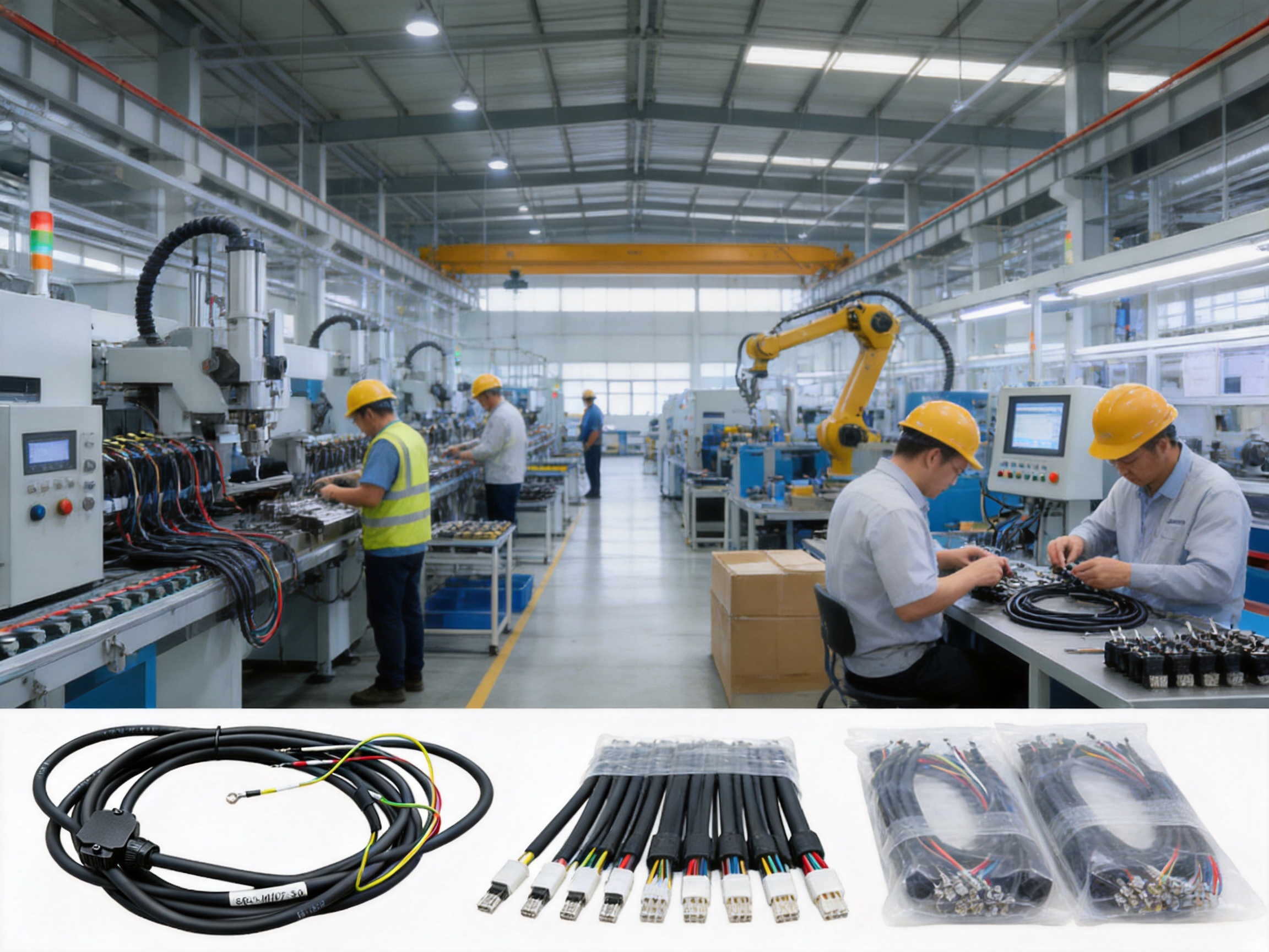
Modern automation depends on the accurate, continuous, and safe transmission of electrical power. Servo motors used in CNC machine tools, robots, packaging systems, textile equipment, printing machinery, and automated production lines must receive stable three-phase power even when exposed to vibration, oil, repeated movement, and long operating cycles. A poorly selected cable can introduce voltage loss, intermittent connections, insulation damage, installation errors, and unplanned downtime. The S6-L-M107-3.0 Servo Power Cable is designed to address these challenges through a combination of flexible pure copper conductors, pre-assembled connection hardware, clear wire identification, protective materials, and systematic quality testing.
This cable is a dedicated power connection assembly for servo drives and servo motors. It is supplied with a black latch-style connector at the drive end and pre-crimped open-barrel terminals plus a grounding ring lug at the motor end. As a result, installers do not need to perform secondary crimping or connector assembly before commissioning. The cable can be connected directly to compatible equipment after verifying the interface, wiring sequence, and electrical specifications.
Beyond its convenient configuration, the product reflects a broader manufacturing approach based on application-specific design. The conductor arrangement, terminal preparation, connector structure, sheath selection, labeling, and inspection process are all intended to support dependable industrial operation. This article examines the cable’s construction, performance advantages, manufacturing strengths, installation value, application range, customization possibilities, and suitability for professional equipment builders and automation integrators.
A servo system normally includes a servo drive, a servo motor, and the cables required to transmit power and control signals between them. The power cable carries the motor’s three-phase output from the drive to the motor. In a typical configuration, the three power conductors are identified as U, V, and W, while a separate protective earth conductor is identified as PE.
Although the basic electrical function appears simple, servo power wiring operates in demanding conditions. A production machine may start and stop repeatedly, accelerate and decelerate rapidly, or move cable assemblies through narrow routing channels. The cable can also be exposed to metal edges, oil mist, vibration, dust, temperature changes, and electromagnetic interference from nearby equipment. A power cable must therefore combine electrical capacity with mechanical flexibility and reliable termination.
Generic power wire may be suitable for fixed installations, but it may not provide the same convenience or reliability for pre-engineered servo systems. A dedicated servo power cable is designed around the interface requirements of industrial drives and motors. The use of clearly identified conductors and prepared terminals helps reduce the possibility of connection errors. The connector and terminals are selected as part of an assembly rather than treated as separate components, helping improve consistency from one installation to the next.
The S6-L-M107-3.0 model is particularly suitable when an equipment manufacturer or service technician needs a ready-to-install connection between a servo drive and motor. Its configuration helps shorten field wiring time while maintaining an organized and professional installation appearance.
The core contains multi-strand pure copper conductors. Multi-strand construction allows the cable to bend more easily than a solid-core conductor of comparable cross-sectional area. This is important in machinery where cables must be routed around frames, through cable channels, or near moving assemblies.
The three phase conductors are represented by red, black, and white wires and correspond to U, V, and W outputs. A yellow-green conductor is provided for protective earth. This color arrangement gives installers a clear visual reference during connection and maintenance. The PE conductor is further supported by a ring lug at the motor end, allowing the grounding connection to be secured to an appropriate grounding point.
The conductor material offers high electrical conductivity and supports efficient power transmission. Pure copper is widely used for industrial power cables because it combines low electrical resistance with good flexibility, thermal performance, and compatibility with common crimping processes. The multi-strand structure also helps reduce mechanical stress on individual strands when the cable is bent during routing or installation.
At the drive end, the cable is equipped with a black square latch-style connector. The connector uses a keyed pin arrangement designed to prevent incorrect insertion. Its locking structure supports secure retention after mating, helping reduce the risk of loosening caused by vibration or equipment movement.
At the motor end, the conductors are terminated with open-barrel crimp terminals. The terminals are supplied already crimped and are marked according to the U, V, W, and PE sequence. The protective earth wire is fitted with a ring lug. This configuration is practical for motors that use screw terminals, stud terminals, or other terminal arrangements requiring direct conductor attachment rather than a multi-pin plug.
| Component | Configuration | Primary Function | Installation Benefit |
|---|---|---|---|
| Phase conductors | Red, black, and white multi-strand pure copper wires | Transmit three-phase motor power | Good conductivity, flexibility, and clear phase identification |
| Protective earth conductor | Yellow-green wire with ring lug | Provide grounding continuity | Supports direct connection to the motor grounding point |
| Drive-end connector | Black square latch-style connector | Connect to the servo drive power terminal | Keyed insertion and secure locking |
| Motor-end terminals | Pre-crimped open-barrel terminals | Connect to motor U, V, and W terminals | Eliminates on-site crimping work |
| Outer sheath | Oil-resistant and abrasion-resistant PVC composite | Protect the internal conductors | Improves suitability for industrial environments |
| Wire labels | Heat-shrink identification labels | Identify U, V, W, and PE | Reduces the likelihood of wiring mistakes |
The first major advantage of the cable is its focus on stable power delivery. Servo motors can experience high current demand during acceleration, braking, rapid positioning, and heavy-load operation. The use of multi-strand pure copper conductors helps provide an efficient conductive path between the drive and motor.
Lower conductor resistance can help reduce transmission losses and unnecessary heat generation when the cable is correctly selected for the motor’s voltage, current, installation length, and operating conditions. Stable power transmission is particularly important in applications where motors operate for long periods or where repeated speed changes place continuous demands on the electrical system.
The cable’s three-phase conductor arrangement is clearly organized around the U, V, and W outputs. This supports standardized installation practices and makes it easier for technicians to trace the power path during inspection. The dedicated PE conductor provides a separate protective grounding route rather than relying on an improvised connection or an incorrectly shared conductor.
Another advantage is the consistency of the supplied assembly. When terminals are crimped manually at the installation site, quality may vary according to tool condition, operator experience, conductor preparation, and inspection discipline. A factory-prepared cable can offer more repeatable termination quality when produced under controlled procedures. This is valuable for machine builders that need to assemble multiple units with consistent wiring performance.
The cable is not intended to replace the need for proper system engineering. The installer must still confirm the servo drive and motor specifications, rated voltage, current, terminal arrangement, cable length, grounding requirements, and environmental conditions. However, once the correct configuration has been established, the prepared assembly reduces unnecessary field work and supports a more controlled electrical installation.
Servo equipment often places greater mechanical demands on a cable than a static electrical cabinet. Even when the cable itself is not part of a high-cycle drag-chain system, it may experience repeated bending during machine movement, adjustment, maintenance, and installation. A flexible multi-strand conductor is better suited to these conditions than a rigid solid conductor.
The cable’s flexible structure helps installers route it around equipment without excessive force. Reduced routing stress can make it easier to maintain appropriate bend radii and avoid sharp kinks. Proper routing remains essential because no cable should be bent beyond its specified limits or crushed by clamps and covers. Nevertheless, the multi-strand design provides a useful margin of handling flexibility during machine assembly and service.
The external PVC composite sheath is described as oil-resistant and abrasion-resistant. Industrial machinery commonly uses lubricants, hydraulic fluids, cutting fluids, cleaning agents, and other substances that can damage unsuitable insulation over time. A sheath designed for improved oil resistance can help preserve the cable’s exterior in workshops and production environments.
Abrasion resistance is also important where the cable passes through protective sleeves, cable trays, machine frames, or equipment openings. Contact with rough surfaces, repeated vibration, or slight movement against nearby parts can wear down an unprotected sheath. A stronger outer layer helps reduce this risk, provided the installation avoids continuous contact with sharp edges or uncontrolled movement.
The sheath is also described as weather-resistant and flame-retardant. These properties broaden the cable’s suitability for industrial locations where temperature variation, humidity, or elevated fire-safety requirements may be present. The cable should still be selected according to the exact environmental rating required by the machine and applicable regulations.
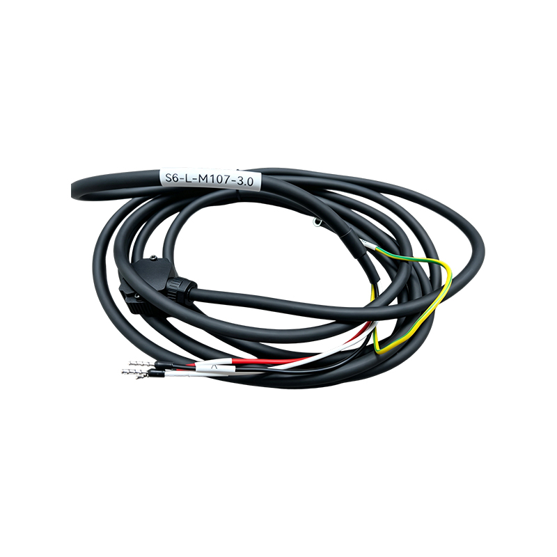
S6-L-M107-3.0 Servo Power Cable
Connection reliability is as important as conductor quality. A cable with excellent copper conductors can still cause system problems if the connector is difficult to mate, easily installed incorrectly, or vulnerable to vibration. The drive-end connector on the S6-L-M107-3.0 uses a keyed pin arrangement intended to prevent mismating.
A keyed connector guides the installer toward the correct orientation. This helps prevent the connector from being forced into the drive terminal in an incorrect position. In a busy production environment, where several connectors may be located close together, physical keying provides an additional layer of protection against wiring errors.
The latch-style design also supports secure retention. After the connector is inserted correctly, the locking mechanism helps maintain the connection during vibration and normal machine operation. A secure latch can reduce the possibility of intermittent contact caused by gradual loosening, accidental cable pulling, or repeated equipment movement.
The black housing provides a distinct visual identity for the drive-end connection. Combined with the keyed structure, the housing makes the assembly easier to recognize during installation and maintenance. A technician can quickly distinguish the prepared drive connection from loose conductors or unrelated control wiring.
At the motor end, the pre-crimped terminals provide a different type of connection flexibility. Many servo motors use individual screw or stud terminals rather than a matching plug. Open-barrel terminals can therefore be attached directly to the relevant motor contacts, while the ring lug provides a stable fastening point for PE grounding.
The terminal surfaces are described as tin-plated. Tin plating can support stable electrical contact and improve resistance to oxidation and corrosion under normal service conditions. The quality of the final connection still depends on correct terminal seating, tightening torque, cleanliness, and compliance with the motor manufacturer’s instructions.
One of the most practical product advantages is that the cable arrives with its terminals and connector already prepared. Traditional field assembly may require cutting the cable to length, stripping the insulation, arranging individual conductors, selecting terminals, performing crimps, installing connector housings, labeling each wire, and testing continuity. Every additional step creates an opportunity for variation or error.
With the prepared assembly, the installer can focus on verification and connection rather than component preparation. The drive-side connector can be mated with the compatible power interface, while the motor-side terminals can be secured to the corresponding U, V, W, and PE points. This can significantly reduce the time required for machine wiring and commissioning.
Pre-assembly is especially useful for equipment manufacturers producing repeated machine configurations. Instead of assigning technicians to reproduce the same cable preparation process for every machine, the manufacturer can specify a consistent cable assembly. This supports standardized work instructions, more predictable labor requirements, and simpler spare-parts management.
The solution can also benefit maintenance departments. A replacement cable that arrives ready for installation can reduce the duration of equipment downtime. Maintenance personnel do not necessarily need to carry specialized crimping tools or prepare loose terminals in the field. The cable can be installed after checking compatibility and following safe isolation procedures.
Clear heat-shrink labels further improve installation efficiency. Each wire end is marked to indicate its sequence, including U, V, W, and PE. Labels are more durable and legible than temporary handwritten markings, especially when the cable is handled repeatedly during machine construction or service.
Reducing installation steps does not mean eliminating inspection. Before energizing the system, technicians should check the phase sequence, terminal tightness, grounding continuity, insulation condition, connector engagement, cable routing, and compatibility with the drive and motor. The prepared design simply makes these checks more straightforward and reduces the number of manual fabrication steps.
Industrial cables are exposed to more than electrical load. They must operate in locations where oil, dust, vibration, movement, humidity, and mechanical contact are part of everyday production. The S6-L-M107-3.0 is designed with materials and assembly features intended to support operation in such environments.
Oil resistance helps protect the sheath when the cable is routed near lubrication systems, machine tools, gearboxes, hydraulic components, or cutting areas. If contaminants remain on the cable for long periods, routine cleaning and inspection are still recommended. Resistance to oil does not mean that the cable can be immersed indefinitely in every chemical substance.
Abrasion resistance helps the sheath withstand normal handling and contact with cable management systems. Installers should keep the cable away from burrs, sharp corners, hot surfaces, and unprotected moving joints. Protective conduits, flexible sleeves, clamps, and cable chains may be required depending on the application.
Vibration is another common source of connection failure. Servo motors and machine tools can generate continuous or intermittent vibration, especially during rapid motion and high-speed operation. The locking connector, secure motor-end terminals, and properly fastened grounding lug work together to support connection stability.
Weather resistance can be useful in workshops with variable temperature and humidity or in equipment that is moved between indoor and semi-exposed areas. The final application must still be evaluated for ultraviolet exposure, water ingress, outdoor installation, and temperature extremes. If the equipment is exposed to conditions beyond the cable’s intended rating, additional protection may be required.
The value of a cable assembly depends not only on its specification but also on the way it is manufactured. Consistent conductor preparation, terminal crimping, connector assembly, labeling, and testing are necessary to produce a dependable product.
The manufacturer operates a modern production base of approximately 5,000 square meters and has more than 50 employees, including quality engineers and research and development technicians with extensive industry experience. This organizational structure supports the coordination of product design, production planning, process control, inspection, and customer service.
The company reports operating 10 automated production lines with a monthly output of up to 10 million meters. High production capacity can be valuable for customers that need both standard products and recurring customized orders. Automated and semi-automated production equipment can also improve repeatability when processes are properly monitored and maintained.
For a servo power cable, manufacturing control typically begins with conductor preparation. Copper conductors must be selected according to the specified construction and processed without damaging individual strands. The conductors are then arranged in the required color sequence and combined with the protective earth wire.
The outer sheath is applied to protect the conductor group. During this stage, process control is important because uneven insulation thickness, surface defects, voids, or dimensional variation can affect the cable’s mechanical and electrical performance. Production inspection helps identify defects before the cable proceeds to termination.
Connector assembly requires careful attention to pin arrangement, insertion depth, housing compatibility, and latch operation. The keyed structure must remain correctly aligned so that the finished connector mates with the intended drive interface. Terminal crimping also requires control of strip length, conductor insertion, crimp height, pull strength, and terminal alignment.
Labels are applied after or during terminal preparation so that the U, V, W, and PE identification remains associated with the correct conductor. Heat-shrink labels can provide a clean and durable marking method when applied under appropriate process conditions.
Quality control does not end with visual inspection. The product information states that each cable undergoes continuity testing, insulation resistance testing, and high-voltage withstand testing before shipment. These tests address different aspects of cable reliability.
| Test | Purpose | Risk Addressed |
|---|---|---|
| Continuity test | Confirm that each conductor and terminal path is electrically continuous | Open circuits, incorrect termination, or broken conductors |
| Insulation resistance test | Evaluate resistance between conductors and between conductors and ground | Insulation damage, contamination, or unintended leakage paths |
| High-voltage withstand test | Apply a controlled test voltage to verify insulation withstand capability | Insulation weakness that could lead to breakdown during service |
| Visual and assembly inspection | Check connector housing, latch, labels, terminals, sheath, and general finish | Incorrect assembly, physical damage, or identification errors |
Testing is especially important for pre-terminated assemblies because the final product contains several connection interfaces. A cable may have acceptable raw materials but still fail if a terminal is incorrectly crimped or a connector pin is misassembled. Full-process inspection helps ensure that the finished assembly, rather than only the cable material, is evaluated.
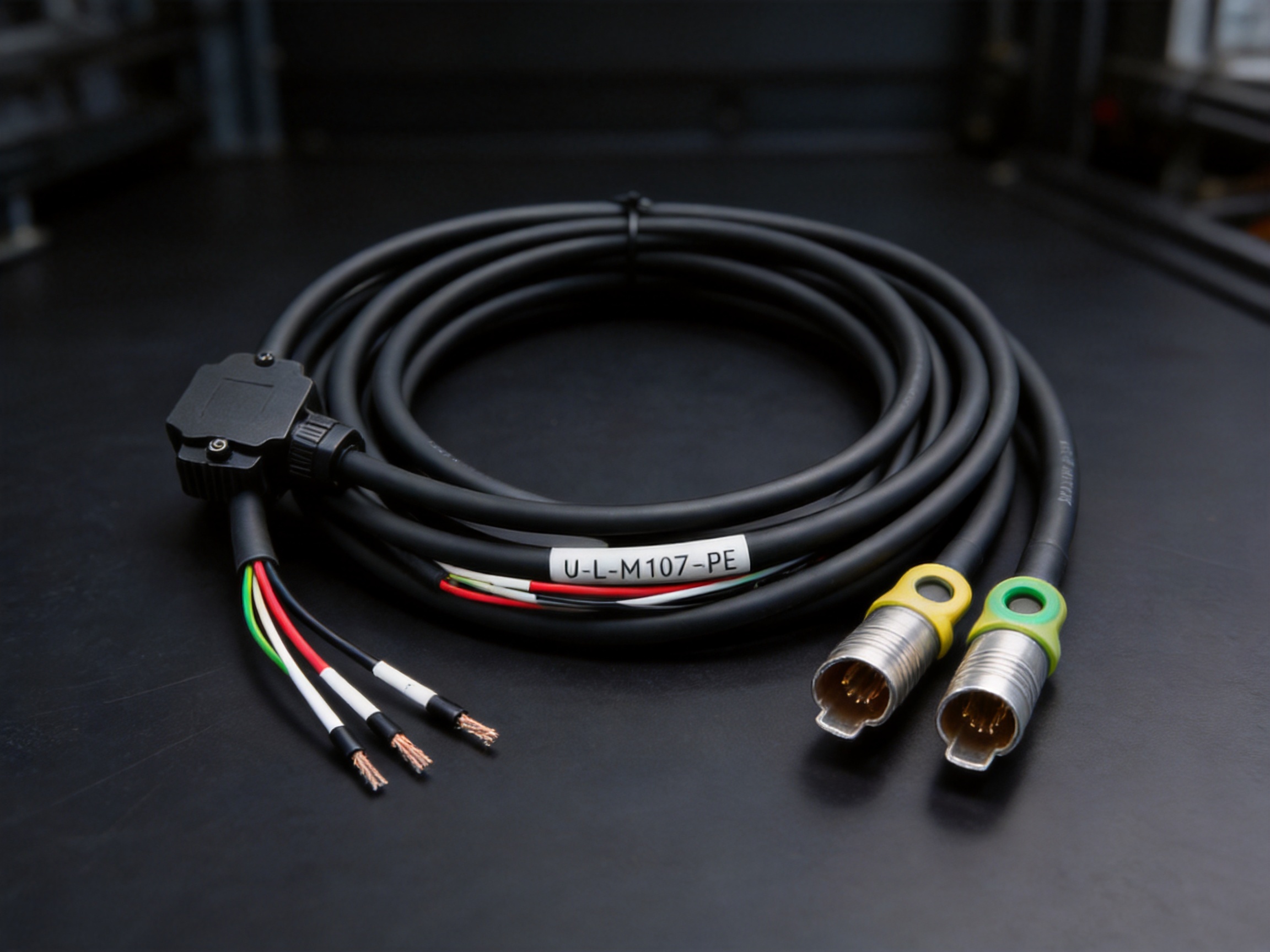
The S6-L-M107-3.0 offers several advantages over a generic cable that is supplied without terminals or a connector. The first is application alignment. Instead of requiring the customer to select individual wires, terminals, housings, and labels, the product combines them into a servo power assembly intended for a defined connection task.
The second advantage is installation consistency. Manual preparation can produce differences in stripping length, crimp quality, wire labeling, and connector assembly from one machine to another. A factory-prepared cable supports a more uniform result and reduces reliance on individual installer technique.
The third advantage is reduced commissioning time. Pre-crimped terminals and a prepared connector allow technicians to complete the physical wiring more quickly. This can help shorten machine assembly schedules and reduce the time needed to return equipment to service after maintenance.
The fourth advantage is improved wiring identification. The color-coded conductors and heat-shrink labels create a clear reference for U, V, W, and PE. Generic cable may require the installer to add identification manually, and temporary markings can become illegible or detached during installation.
The fifth advantage is connection security. The keyed latch connector helps prevent incorrect mating and supports retention under vibration. A generic cable with separate loose conductors may not provide the same level of mechanical guidance or connector integration.
The sixth advantage is reduced tooling demand. A customer that purchases loose cable and terminals may need wire strippers, calibrated crimp tools, connector insertion tools, heat-shrink equipment, and electrical test instruments. A finished cable assembly reduces the amount of field equipment required for routine installation.
The seventh advantage is customization. The supplier can adjust cable length, connector model, and terminal type according to equipment interface requirements. This is useful when different servo drive brands or motor families use different connection structures. Rather than forcing customers to modify a standard cable, the assembly can be developed around the intended equipment configuration.
These advantages should be considered alongside proper technical verification. A pre-terminated product is beneficial only when its connector, terminal, length, conductor size, and electrical characteristics match the target servo system. Professional selection remains essential.
Servo systems are not standardized around one universal connector. Different drive manufacturers and motor suppliers may use different pin layouts, housing dimensions, terminal styles, grounding methods, and cable requirements. For this reason, customization capability is an important supplier strength.
The manufacturer supports customization of cable length, connector model, and terminal type. Cable length can be adjusted to suit the physical distance between the control cabinet and motor while avoiding unnecessary excess cable. The correct length can support cleaner routing, better cable management, and reduced material waste.
Connector customization allows the assembly to match the customer’s drive interface. The connector must be selected based on the exact part specification, pin arrangement, locking structure, and electrical rating. A professional supplier can review drawings, samples, or equipment information before confirming the design.
Terminal customization is also important at the motor end. Some motors use open-barrel terminals, while others require ring terminals, fork terminals, plugs, or proprietary connection systems. Terminal material, plating, size, crimp method, and insulation requirements can be specified according to the application.
OEM and ODM support can be valuable for machine manufacturers that want their cable assemblies to follow internal standards. The supplier can work from customer drawings or samples and provide a tailored cable design. This approach can help create consistent spare parts and simplify procurement across multiple machine models.
The reported standard lead time for customized products is typically 7 to 20 days, depending on the design and order requirements. Customers should confirm the actual schedule, prototype needs, test documentation, minimum order quantities, and approval process before placing a production order.
CNC machine tools rely on servo motors for axis positioning, spindle control, tool movement, and other precision operations. Their electrical cabinets and moving axes create a need for organized, durable, and properly identified power cables. The S6-L-M107-3.0 can be used for compatible servo motor power connections where its electrical and mechanical specifications meet the equipment requirements.
In machining environments, oil, cutting fluid, metal chips, and vibration are common. The oil-resistant and abrasion-resistant sheath can provide useful protection, while proper cable routing and protective management remain necessary to prevent contact with chips and sharp machine components.
Industrial robots use servo motors at joints, external axes, and auxiliary mechanisms. Robot cables may experience repeated bending and movement, so cable selection must take account of the exact motion pattern, cycle frequency, bend radius, and cable-management system. The flexible multi-strand construction is helpful for handling and routing, but applications involving continuous torsion or high-cycle dress packs should be reviewed carefully to confirm suitability.
Pre-identified conductors and prepared terminals can simplify robot installation and replacement. Maintenance technicians can more quickly trace the power connection and verify the grounding path during service.
Automated production lines may contain many servo drives and motors distributed across conveyors, feeders, positioning systems, inspection stations, and material-handling modules. Standardized cable assemblies help maintain consistency across repeated stations.
When each assembly is labeled and tested before shipment, system integrators can reduce the amount of wiring fabrication performed during line installation. This can be particularly valuable when the production line is assembled under a strict schedule or at multiple locations.
Packaging equipment often performs rapid and repetitive movement. Servo motors control film feeding, cutting, sealing, indexing, labeling, and product positioning. The power cable must remain secure while the machine cycles at high speed.
The latch connector and pre-crimped terminals support quick assembly, while the flexible conductors help simplify routing around compact machine frames. The cable’s environmental protection can also be useful where packaging machinery is cleaned frequently or operates near lubricated mechanisms.
Textile and printing machinery may require precise motor synchronization and stable operation over long production periods. Cable routing can be complicated by rollers, moving carriages, narrow frames, and frequent equipment adjustments. A flexible, clearly labeled power assembly can support faster installation and maintenance.
Electronic manufacturing systems often include precision stages, pick-and-place mechanisms, inspection modules, and automated handling equipment. These machines may have dense wiring layouts in which identification and connector security are especially important. The prepared servo cable helps organize the power side of the system and supports efficient service work.
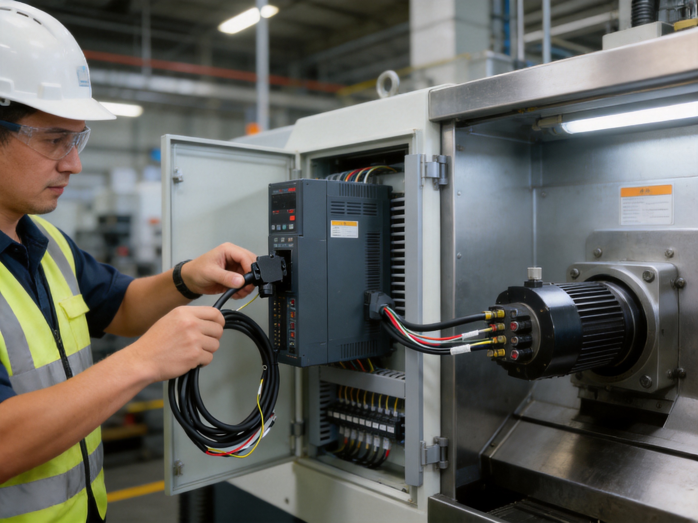
Before installation, confirm that the cable is compatible with the servo drive and motor. Check the connector model, pin arrangement, conductor size, rated voltage, current requirement, cable length, terminal style, and grounding method. Do not rely only on physical appearance because similar connectors can have different internal wiring configurations.
Disconnect and isolate all power sources before connecting the cable. Follow the safety procedures specified by the equipment manufacturer and applicable electrical regulations. Servo drives may retain hazardous voltage after power is removed, so the required discharge time and verification procedure must be observed.
Connect the drive-end connector in the correct orientation. Use the keyed structure rather than forcing the connector into place. Confirm that the latch is fully engaged and that the connector cannot be easily withdrawn without releasing the locking mechanism.
At the motor end, connect the terminals according to the identified U, V, and W sequence. Attach the PE ring lug to the correct grounding point and tighten all fasteners according to the motor manufacturer’s recommended torque. Do not substitute the protective earth connection with an improvised attachment.
Route the cable so that it is protected from sharp edges, excessive heat, crushing, tensile loading, and unnecessary bending. Maintain an appropriate bend radius and use clamps or cable-management systems that support the cable without compressing the sheath. Avoid placing heavy components on the cable or using it as a lifting handle.
After installation, inspect the complete route and verify that the cable does not interfere with moving machine components. Check the connector latch, terminal seating, grounding attachment, labels, and sheath condition. Perform continuity and insulation checks where required by the system commissioning procedure.
Before full-speed operation, conduct a controlled test run. Observe the motor direction, drive alarms, connector stability, cable movement, and any unusual heating or noise. If the motor rotates in the wrong direction or the drive reports an error, disconnect power and investigate the wiring rather than making live adjustments.
Routine inspection can help extend the service life of a servo power cable. Maintenance personnel should examine the outer sheath for cuts, flattening, abrasion, swelling, discoloration, or chemical damage. Any sign of exposed conductor or compromised insulation should be treated as a potential safety issue.
Inspect the drive-end connector for cracks, damaged latch components, contamination, loose engagement, or signs of overheating. The motor-end terminals should be checked for secure fastening, corrosion, deformation, and conductor pullout. The PE ring lug deserves particular attention because reliable grounding is essential for equipment safety.
Keep the cable clean according to the cable and machine manufacturer’s recommendations. Do not use cleaning agents that may attack the PVC sheath or terminal materials. Where the cable operates near oil or cutting fluid, remove accumulated contamination during scheduled maintenance.
Repeated cable movement should be reviewed if the equipment experiences unexpected faults. Check whether the cable is rubbing against a frame, bending at an excessively tight radius, or being pulled during machine travel. Correcting the routing problem may be more effective than repeatedly replacing the cable.
When a cable must be replaced, use an assembly with matching electrical and mechanical specifications. A cable that appears similar but has a different pin arrangement, conductor size, terminal structure, or grounding configuration may create serious equipment and safety risks.
Anhui Zhishang Cable Technology Co., Ltd. integrates research and development, production, and sales of wires and cables. Its location in Xuanzhou District, Xuancheng City, Anhui Province, places the company within the broader Yangtze River Delta industrial region, which provides access to manufacturing resources, engineering talent, and logistics networks.
The company’s reported production base covers approximately 5,000 square meters and includes 10 automated production lines. A monthly production capacity of up to 10 million meters provides a foundation for serving both standard cable demand and larger recurring orders. Production scale can also support more efficient material planning and process specialization.
More than 50 employees are involved in the company’s operations, including quality engineers and research and development technicians with more than 10 years of industry experience. Such personnel can contribute to connector selection, conductor construction, terminal crimping methods, production troubleshooting, inspection planning, and customized product development.
The company emphasizes full-core and full-length pure copper specifications, test reports, and warranty support for standard cable models. These capabilities are relevant to customers that require traceable product information and structured after-sales support.
Its stated quality philosophy emphasizes quality orientation, integrity, and stability. In the cable industry, these principles are reflected in material consistency, accurate assembly, reliable testing, delivery discipline, and responsiveness to technical questions. For a specialized servo cable, technical communication is particularly important because compatibility is determined by more than cable appearance alone.
The company also supports OEM and ODM development based on customer drawings or samples. This enables machine manufacturers, system integrators, distributors, and maintenance organizations to request cable assemblies adapted to their own equipment interfaces and production standards.
The product information states that the cable has passed China 3C and European CE certification requirements. Customers should request and review the relevant certificates, declarations, test reports, and product specifications for the exact model and configuration being purchased. Certification status can vary by product version, connector arrangement, voltage rating, or customized design.
Technical documentation should ideally identify the conductor construction, rated voltage, current capacity, operating temperature, sheath material, bending guidance, terminal type, connector model, and applicable test methods. For customized assemblies, the approved drawing should also show the pin sequence, wire colors, terminal references, cable length, and grounding arrangement.
Document control is important for industrial customers. A machine builder may need to retain cable drawings, incoming inspection records, batch information, certificates, and replacement specifications for the life of the equipment. A professional supplier can help reduce confusion by providing consistent part numbers and revision information.
Testing before shipment provides useful assurance, but it does not remove the need for incoming inspection. The buyer should verify the quantity, appearance, labels, connector type, terminal arrangement, and documentation upon receipt. Any discrepancy should be reported before the cable is installed.
Engineering teams should begin by identifying the exact servo drive and motor models. The drive-side connector should be matched to the drive’s power output interface, while the motor-side terminals should be matched to the motor’s U, V, W, and PE connection points.
The required cable length should be calculated from the actual routing path rather than the straight-line distance. Include sufficient allowance for service loops and machine movement, but avoid excessive slack that can become entangled or interfere with moving parts.
Electrical requirements should include operating voltage, continuous current, peak current, duty cycle, ambient temperature, installation method, and any applicable shielding or electromagnetic compatibility requirements. The product described here is a servo power cable; it should not be confused with a feedback, encoder, brake, or communication cable.
Environmental requirements should identify exposure to oil, coolant, water, dust, sunlight, chemicals, vibration, and repeated movement. If the cable will be installed in a drag chain or robot dress pack, the customer should provide the motion profile so that the supplier can confirm whether the standard construction is appropriate or whether a specialized flexible cable is required.
Procurement teams should also confirm production lead time, sample availability, customization charges, packaging, test documentation, warranty terms, and spare-parts supply. For repeat orders, an approved sample and controlled drawing can help prevent changes to connector pinout or terminal configuration.
The S6-L-M107-3.0 Servo Power Cable combines several features that directly address common industrial wiring problems. Its pure copper multi-strand conductors support efficient power transfer and flexible handling. Its color arrangement and heat-shrink labels make the phase and grounding conductors easier to identify. Its keyed latch connector helps guide correct mating and maintain connection security. Its pre-crimped terminals and grounding ring lug reduce field fabrication work.
The oil-resistant and abrasion-resistant sheath provides a useful level of protection for workshops, production lines, machine tools, and automation equipment. The factory testing process adds another layer of confidence by checking continuity, insulation resistance, and high-voltage withstand capability before shipment.
Compared with assembling loose cable and terminals at the installation site, the prepared product can reduce labor, tooling requirements, wiring variation, and commissioning time. Compared with an unverified generic assembly, it provides a more organized and application-focused solution. Compared with a fixed standard product that cannot match different equipment interfaces, its customization capability offers greater flexibility for OEM and system integration projects.
The strongest results will be achieved when the cable is selected through a complete engineering review. Compatibility, routing, electrical loading, grounding, environmental exposure, and movement requirements must all be considered. With those conditions properly confirmed, the product can serve as a dependable connection component in a wide range of servo-driven machinery.
The cable is designed to connect a compatible servo drive to a servo motor for three-phase power transmission. It includes U, V, and W phase conductors plus a protective earth conductor.
The assembly includes red, black, and white power wires for U, V, and W, together with a yellow-green PE grounding wire. The exact conductor size and electrical rating should be confirmed against the approved product specification.
The drive end uses a black square latch-style connector with a keyed pin arrangement. The keyed design helps prevent incorrect insertion, while the latch supports secure retention.
The motor end is supplied with pre-crimped open-barrel terminals for the phase conductors and a ring lug for the protective earth connection. The terminals are labeled according to the U, V, W, and PE sequence.
No secondary crimping is normally required because the terminals are prepared before shipment. The customer should still verify compatibility, terminal seating, and tightening requirements before energizing the system.
Yes. The manufacturer supports customization of cable length according to the customer’s equipment and routing requirements.
The connector model can be customized according to the customer’s drive interface. The exact drive model, connector drawing, pinout, and electrical requirements should be provided for confirmation.
It is intended for compatible servo power connections in CNC machine tools and similar industrial equipment. The installer must confirm the required current, voltage, cable length, routing method, and environmental conditions.
The cable has a flexible multi-strand construction, but continuous drag-chain or robotic torsion applications require a detailed motion assessment. The bend radius, travel distance, cycle rate, torsion, and cable-management system should be reviewed before selection.
The stated testing process includes continuity testing, insulation resistance testing, and high-voltage withstand testing. Visual and assembly inspections are also important for verifying labels, terminals, connector engagement, and sheath condition.
The outer sheath is described as oil-resistant, abrasion-resistant, weather-resistant, and flame-retardant. The final application should still be evaluated for chemicals, water exposure, temperature, ultraviolet radiation, and mechanical movement.
Pure copper offers high electrical conductivity, low resistance, and good compatibility with flexible multi-strand construction. These properties support stable power transmission when the conductor size is correctly matched to the application.
The PE conductor provides a protective grounding path. The yellow-green wire and ring lug help connect the motor housing or designated grounding point to the system protective earth network.
No. Factory testing improves product assurance, but the completed machine should still undergo installation checks, grounding verification, insulation checks where required, phase-sequence confirmation, and controlled operational testing.
Useful information includes the servo drive and motor models, connector drawings, pin arrangement, required cable length, conductor specification, terminal type, grounding method, installation environment, movement conditions, quantity, and required documentation.
The S6-L-M107-3.0 Servo Power Cable is designed as a complete, installation-ready connection solution for compatible servo drive and motor systems. Its multi-strand pure copper conductors support efficient three-phase power transmission, while the separate PE conductor provides a dedicated grounding path. The keyed latch connector improves mating accuracy and retention, and the pre-crimped motor-end terminals reduce installation time and field fabrication requirements.
Its oil-resistant and abrasion-resistant sheath, clear labeling, tin-plated terminal surfaces, and full-process testing make it suitable for many industrial environments. The product is particularly relevant to CNC machines, industrial robots, automated production lines, packaging equipment, textile machinery, printing systems, and electronics manufacturing equipment.
The supplier’s production capacity, automated manufacturing lines, engineering personnel, testing procedures, and OEM/ODM support further strengthen the product’s value for industrial customers. By combining standardized production with customization capability, the company can support both regular replacement needs and specialized equipment projects.
For best results, customers should treat the cable as part of a complete servo system rather than as an isolated wiring component. Correct selection, safe installation, suitable routing, proper grounding, and regular inspection are essential. When these requirements are addressed, the S6-L-M107-3.0 can help provide stable, organized, and dependable power connections for modern automated machinery.
1. International Electrotechnical Commission. General principles for low-voltage cable construction, insulation, and electrical testing.
2. International Electrotechnical Commission. Guidance for electrical equipment of industrial machines and protective bonding practices.
3. International Electrotechnical Commission. Recommendations for cable assemblies, conductor identification, and electrical safety verification.
4. China Compulsory Certification framework. General requirements for applicable wire and cable products.
5. European conformity assessment principles for low-voltage electrical equipment and industrial cable assemblies.
6. Manufacturer-provided product information for the S6-L-M107-3.0 Servo Power Cable.
7. Manufacturer-provided information concerning production capacity, OEM/ODM services, quality testing, and customized wire and cable solutions.

We firmly believe that good cables are not only a competition of materials, but also a reflection of craftsmanship, quality, and responsibility.

Links
Product
Send Inquiry
No. 29 Sankeshu Road, Xuanzhou District, Xuancheng City, Anhui Province, China
+86-18621104555/+86-563-2622999
 Electrical Cable Manufacturer
OEM/ODM Wire and Cable Solutions
 English
 Español
 عربى
 русский